
Description
Hard-Numbers: Technical Specifications
- Input Signal: 4-20 mA (flow rate), 0-10 VDC (optional voltage input)
- Display Type: 6-digit LCD with backlight (0.5″ character height)
- Display Units: Programmable (GPM, LPM, m3/h, ft3/s, etc.)
- Flow Range: 0-9999 (user-configurable scaling)
- Accuracy: ±0.1% of reading ± 1 digit (display accuracy only)
- Output Relays: 2 x SPDT form C (5 A @ 250 VAC resistive)
- Alarm Functions: High flow, low flow, totalizer batch complete
- Power Supply: 120/240 VAC, 50/60 Hz (auto-ranging)
- Operating Temperature: 0°C to 50°C (32°F to 122°F)
- Storage Temperature: -20°C to 70°C (-4°F to 158°F)
- Enclosure Rating: NEMA 4X (IP66) weatherproof
- Material Construction: Polycarbonate enclosure, stainless steel terminals
- Programming: Front-panel keypad or PC configuration software
- Communication: Optional RS-485 Modbus (via accessory module)

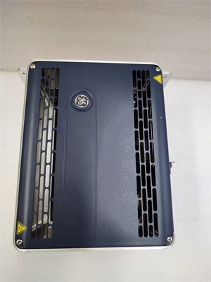
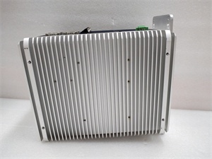
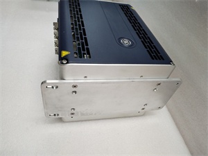
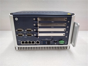
GE 04240FD11234A
The Real-World Problem It Solves
Operators need to see flow rates at the process line without walking back to the control room. The 04240FD11234A provides local digital indication with programmable scaling, eliminating analog gauges that drift and require manual conversion.
Where you’ll typically find it:
- Chemical dosing pump discharge lines
- Cooling water flow monitoring stations
- Wastewater treatment flow control panels
Bottom line: It’s a rugged local indicator that survives washdown environments and provides relay outputs for alarms.
Hardware Architecture & Under-the-Hood Logic
The 04240FD11234A is a standalone digital indicator with an embedded microcontroller for signal processing. The 4-20 mA input is converted to a digital value via a 16-bit ADC, then scaled to user-programmable engineering units displayed on the LCD. Two internal relays provide alarm outputs configurable for high/low flow or batch totalization. The microcontroller stores configuration parameters (scaling, alarm setpoints, relay logic) in non-volatile memory.
Signal flow:
- 4-20 mA input passes through input protection and filtering circuit
- ADC converts analog signal to digital value
- Microcontroller applies scaling factor to convert to engineering units
- Flow rate displayed on LCD backlighted display
- Totalizer accumulates flow volume over time
- Alarm logic compares flow rate to programmable setpoints
- Relays energize/de-energize based on alarm status
- Configuration saved to non-volatile memory
- RS-485 Modbus communication (if enabled) streams data
GE 04240FD11234A
Field Service Pitfalls: What Rookies Get Wrong
Incorrect scaling causes display errorsThe indicator must match the transmitter’s range. I’ve seen technicians leave the default scaling, displaying flow in GPM when the transmitter is configured for LPM.
- Field Rule: Program the indicator to match the transmitter’s full-scale range. For a 4-20 mA transmitter with 0-100 GPM range, set indicator min/max to 0-100 GPM. Test by applying 4 mA (should display 0) and 20 mA (should display 100). Document scaling values in your field records.
Connecting to the wrong power source damages electronicsThe indicator is designed for AC line voltage. I’ve seen technicians wire 24 VDC to the 120/240 VAC input, destroying the power supply instantly.
- Field Rule: Verify the power supply matches the indicator’s rating. For 120 VAC plants, use a grounded 120 VAC supply. For DC applications, specify the DC variant of the indicator. Test power supply voltage with a multimeter before wiring. Check the nameplate and confirm voltage range.
Ignoring relay ratings causes contact weldingThe relays are rated for 5 A resistive load. I’ve seen technicians wire 10 A inductive loads (motors, solenoid valves) directly to the relay contacts, causing contact welding and relay replacement.
- Field Rule: Check relay contact ratings before connecting loads. For loads over 5 A or inductive loads, use an interposing contactor. If you must drive inductive loads directly, add a snubber circuit or RC network across the contacts. Document load type and current in your maintenance log.
Improper grounding causes display flickering and erratic readingsThe indicator is sensitive to ground loops and electrical noise. I’ve seen displays flicker or read randomly because the shield was connected at both ends.
- Field Rule: Ground the indicator chassis to the cabinet ground at a single point. Terminate the shield of the 4-20 mA signal at the indicator end only. Never connect the shield to ground at both ends. Measure ground potential between the indicator ground and field transmitter ground—should be less than 1 VAC.
Forgotten to calibrate the totalizer causes tracking errorsThe totalizer accumulates flow volume over time. I’ve seen technicians forget to reset the totalizer after maintenance, causing batch errors and production discrepancies.
- Field Rule: Reset the totalizer to zero after any maintenance or batch change. Configure the totalizer units to match your production requirements (gallons, liters, cubic meters). Document the totalizer reset date and batch number in your production records. Consider installing an external totalizer with printing capability if batch tracking is critical.
Commercial Availability & Pricing Note
Please note: The listed price is for reference only and is not binding. Final pricing and terms are subject to negotiation based on current market conditions and availability.


