
Description
Hard-Numbers: Technical Specifications
- Series: I/A Series Fieldbus
- Product Type: Communication 2 Mbps Fiber Optic Fieldbus Extender
- Fiber Type Required: Multimode, graded-index glass fiber (62.5 μm core / 125 μm cladding, 0.275 NA)
- Maximum Transmission Distance: 2 km (1.24 miles) per fiber segment between baseplates
- Transmission Rate: 2 Mbps over HDLC Fieldbus protocol
- Maximum Allowable Signal Loss: 1 dB per km at 1300 nm; 3.6 dB per km at 850 nm
- Connectors Required: ST-type connectors
- Redundancy Support: Configurable as redundant pair (two FCM2F2 modules per baseplate for redundancy)
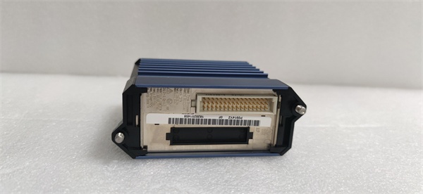
- Mounting: Mounts on 200 Series FBM baseplates (supports DIN rail or 19-inch rack mounting)
- Power Supply: 24 V DC +5%, -10%
- Power Consumption: 5 W (maximum) at 24 V DC
- Heat Dissipation: 5 W (maximum) at 24 V DC
- Operating Temperature: -20°C to +70°C (-4°F to +158°F)
- Storage Temperature: -40°C to +70°C (-40°F to +158°F)
- Relative Humidity: 5% to 95% non-condensing
- Operating Altitude: -300 m to +3,000 m
- Storage Altitude: -300 m to +12,000 m
- Contamination Rating: Class G3 (Harsh) per ISA S71.04; Pollution degree 2 per IEC 664-1
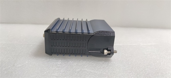
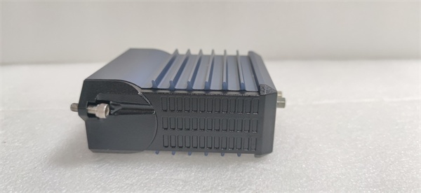
- Dimensions: 102 mm (H) × 45 mm (W) × 104 mm (D) (4 in × 1.75 in × 4.11 in)
- Weight: 284 g (10 oz)
- Indicators: Red and green LEDs for operational status; Amber LEDs for data traffic and direction
- Certifications: UL/UL-C listed for Class I, Groups A-D; Division 2; Temperature code T4; CENELEC certified EEx nA IIC T4 for Zone 2; CE marked; ATEX directive 94/9/EC compliant
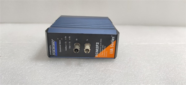
FOXBORO FCM2F2
The Real-World Problem It Solves
In industrial environments, long-distance copper fieldbus runs suffer from EMI/RFI noise, ground potential differences, and lightning-induced surges that corrupt communication signals and damage equipment. Additionally, extending twisted-pair fieldbus beyond 60 meters (200 feet) requires expensive shielded cable and is prone to interference. The FCM2F2 eliminates these problems by converting the Fieldbus signal to fiber optic, providing complete electrical isolation, immunity to electromagnetic interference, and lightning protection while extending communication up to 2 kilometers per segment.
Where you’ll typically find it:
- Chemical and petrochemical plants with remote I/O cabinets in hazardous areas
- Power generation facilities where control rooms are far from field devices
- Steel mills and foundries with high EMI from electric furnaces and welders
- Large manufacturing plants with distributed I/O across multiple buildings
- Outdoor installations exposed to lightning risks
Bottom line: It provides reliable, long-distance fieldbus extension with complete electrical isolation and EMI immunity.
Hardware Architecture & Under-the-Hood Logic
The FCM2F2 acts as a Fieldbus-to-fiber media converter that transparently bridges the I/A Series module Fieldbus between local and remote baseplates. In a redundant configuration, paired FCM2F2 modules ensure automatic failover.
- Fieldbus signals from the I/A Series control station enter via the twisted-pair Module Fieldbus connector on the baseplate.
- The FCM2F2 receives HDLC Fieldbus frames and converts electrical signals to optical signals for fiber transmission.
- Optical transceivers transmit and receive data over multimode fiber (ST connectors) at 2 Mbps.
- At the remote end, a paired FCM2F2 converts optical signals back to electrical Fieldbus signals.
- Remote FBM I/O modules communicate transparently with the host control system over the fiber link.
- In redundant configurations, both FCM2F2 modules monitor traffic; if the primary fails, the secondary takes over automatically.
- Front-panel LEDs indicate power status, Fieldbus activity, fiber link integrity, and module health.
- The module can be hot-swapped—removed or replaced without powering down the baseplate.
- Total system fiber distance across all segments cannot exceed 10 km (3 segments max connecting up to 4 baseplates); the FCM2F2’s 2 km capability per segment fits within this architecture.
FOXBORO FCM2F2
Field Service Pitfalls: What Rookies Get Wrong
Using Wrong Fiber TypeRookies install single-mode fiber instead of the required multimode graded-index fiber (62.5/125 μm, 0.275 NA). This causes signal loss or complete link failure due to core diameter mismatch.
- Field Rule: Always verify fiber specifications before installation. Use only multimode graded-index fiber with 62.5 μm core, 125 μm cladding, and 0.275 NA. Single-mode fiber is for FCM2F10 only.
Mismatched FCM2F Versions at Each EndTechnicians pair an FCM2F2 with an FCM2F4 or FCM2F10 on opposite ends of the fiber link. Different transceiver types cause incompatibility and communication failure.
- Quick Fix: Both ends of the fiber link must use identical FCM2F models. If you need a 4 km link, use FCM2F4 at both ends; for 2 km, use FCM2F2 at both ends.
Exceeding Total System Distance LimitNew engineers assume each 2 km segment is independent and deploy three 2 km segments in series, totaling 6 km—which violates the 10 km maximum system distance or segment-specific limits for the model.
- Field Rule: While FCM2F2 supports 2 km per segment, the entire system (all fiber segments combined) must not exceed 10 km when using FCM2F4/FCM2F10 in mixed configurations. Plan total distance before deployment.
Improper Redundant Pair MountingRookies install redundant FCM2F2 modules in non-adjacent slots on the baseplate, preventing proper synchronization and failover functionality.
- Field Rule: Redundant FCM2F2s must be mounted in the first or last adjacent slots on the baseplate. Follow the mounting diagram in the installation manual.
Using Twisted-Pair Beyond 60 Meters Without FCMsTechnicians run standard shielded twisted-pair fieldbus cable beyond 60 meters (200 feet) to save cost. Signal degradation, noise, and timing violations cause intermittent communication failures.
- Quick Fix: For distances over 60 meters, always use FCM2F modules with fiber optic cabling. Do not extend twisted-pair fieldbus beyond 60 meters under any circumstances.
Ignoring Signal Loss Limits During InstallationInstallers don’t measure fiber attenuation during commissioning. Excessive signal loss from dirty connectors, poor splices, or aging fiber causes intermittent communication.
- Field Rule: Verify signal loss is within 1 dB per km at 1300 nm (or 3.6 dB per km at 850 nm) for each fiber segment. Use an optical power meter for validation.
Please note: The listed price is for reference only and is not binding. Final pricing and terms are subject to negotiation based on current market conditions and availability.


