
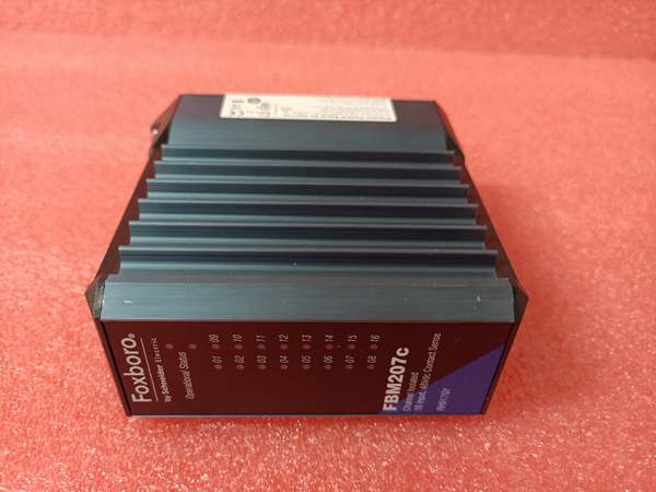
Description
Hard-Numbers: Technical Specifications
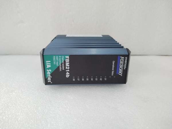
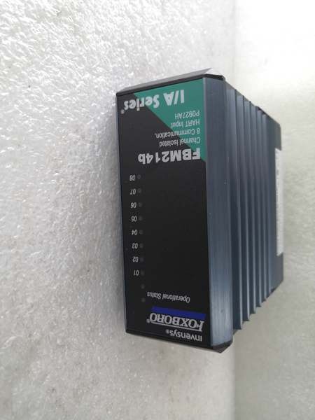
- Series: I/A Series Fieldbus
- Input Channels: 8 (independent, isolated)
- Input Range: 4-20mA (1-21mA extended range)
- Accuracy: ±0.1% of span
- Resolution: 16-bit
- Isolation Rating: 1500 VDC channel-to-channel, 1500 VDC channel-to-system
- Power Supply: 24V DC fieldbus power
- Power Draw: 12W typical
- Operating Temperature: -40°C to +70°C
- Storage Temperature: -40°C to +85°C
- Relative Humidity: 5% to 95% non-condensing
- Certifications: CE, UL, CSA, FM, ATEX, IECEx

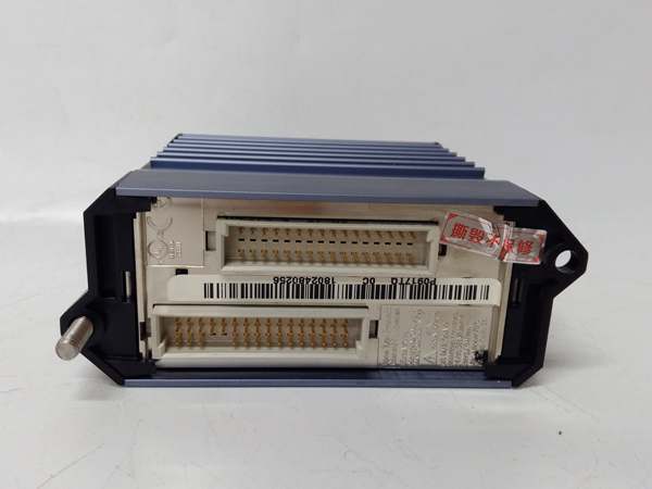
FOXBORO FBM215
The Real-World Problem It Solves
Ground loops and noise corrupt analog measurements in industrial environments. Non-isolated input cards let ground potential differences between field devices distort readings, causing control loop instability. The FBM232 provides per-channel isolation eliminating ground loops, 16-bit resolution for accurate measurement, and digital diagnostics for reliable process variable monitoring across all 8 channels.
Where you’ll typically find it:
- Pressure transmitter monitoring in chemical process plants
- Flow meter inputs in refinery operations
- Temperature transmitter inputs in power generation
- Level transmitter measurement in storage tanks
Bottom line: It delivers accurate, isolated analog input for reliable process control.
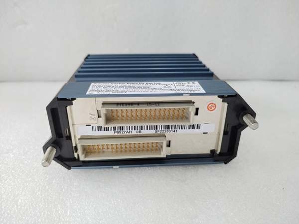
Hardware Architecture & Under-the-Hood Logic
This analog input module contains isolated A/D converters and a microprocessor for signal processing and diagnostics. Each channel has independent isolation barriers, preventing ground potential differences between field devices from affecting measurements. The module communicates over the Foxboro fieldbus to the I/A Series control system.
- 4-20mA signals from field transmitters enter through the terminal block and pass through 250Ω shunt resistors.
- Voltage drops across the shunt resistors are converted to digital values by isolated A/D converters per channel.
- The microprocessor applies scaling and linearization to raw values based on configured range and engineering units.
- Processed analog values are transmitted over the fieldbus to the I/A Series controller.
- Diagnostics circuits monitor input current, open circuits, short circuits, and wiring faults per channel.
- Watchdog timers monitor microprocessor health, triggering fault alerts if system integrity is compromised.
FOXBORO FBM215
Field Service Pitfalls: What Rookies Get Wrong
Mixed Grounding on Isolated InputsNew engineers ground the loop return side at both the module and the field device. Ground potential differences create circulating currents through the isolation barrier, corrupting analog measurements and causing reading drift.
- Field Rule: For isolated inputs, ground the loop return at the module end only. If the field device requires grounding, verify grounding potentials are within 1V. Never create ground loops through isolated channels.
Incorrect Input Range ConfigurationRookies configure the module for a narrow 4-20mA range when field devices support extended ranges. Fault signals above 20mA that indicate device problems get clipped, hiding diagnostic information from operators.
- Quick Fix: Configure input range to match field device capabilities. Use extended range (1-21mA) when devices support fault signals above 20mA. Verify alarm setpoints capture fault conditions.
Ignoring Overrange Diagnostic AlarmsTechnicians ignore overrange alarms during commissioning, assuming they’re temporary calibration issues. Persistent overrange conditions indicate wiring faults, failed transmitters, or incorrect scaling that corrupt control loop performance.
- Field Rule: Address all diagnostic alarms immediately during commissioning using I/A Series diagnostic tools. Verify each channel operates within range before putting the loop into service. Document alarm conditions and resolutions for future reference.
Poor Terminal Wiring on High-Density ModulesRookies wire all 8 channels into tight terminal blocks without considering maintenance access. Testing individual channels becomes difficult during troubleshooting, and wire damage occurs from crowding.
- Field Rule: Use properly sized terminal blocks with adequate spacing. Label wires clearly at both ends. Leave sufficient slack for individual wire removal. Document channel assignments and transmitter tag numbers for quick reference.
Please note: The listed price is for reference only and is not binding. Final pricing and terms are subject to negotiation based on current market conditions and availability.


