
Description
Hard-Numbers: Technical Specifications
- Series: I/A Series Fieldbus
- Input Channels: 8 (independent, isolated)
- Input Signal Range: 0-24V DC (typical)
- Frequency Range: 0-10 kHz (configurable up to 20 kHz)
- Counter Resolution: 32-bit (4,294,967,295 counts)
- Counter Modes: Totalize, Frequency, Rate, Pulse Width
- Input Filter: 0.1 ms typical (configurable 0.01-10 ms)
- Isolation Rating: 1500 VDC channel-to-channel, 1500 VDC channel-to-system
- Power Supply: 24V DC fieldbus power
- Power Draw: 10W typical
- Operating Temperature: -40°C to +70°C
- Storage Temperature: -40°C to +85°C
- Relative Humidity: 5% to 95% non-condensing
- Certifications: CE, UL, CSA, FM, ATEX, IECEx
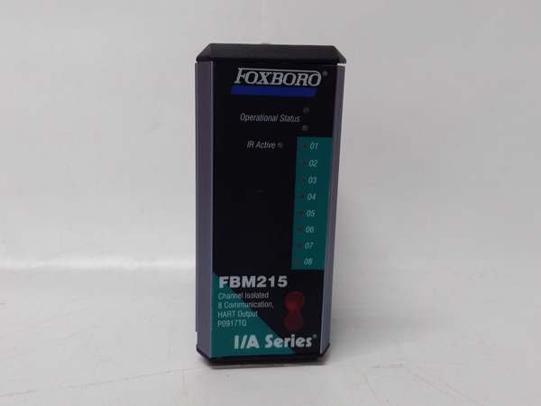
FOXBORO FBM215
The Real-World Problem It Solves
Process measurements from pulse-output devices need accurate counting and frequency measurement. Standard digital input cards lack counter resolution and frequency response, leading to inaccurate flow and speed data. The FBM218 provides high-speed pulse counting with configurable counter modes, enabling accurate flow measurement, tachometer speed monitoring, and position encoder tracking across 8 isolated channels.
Where you’ll typically find it:
- Turbine flow meter totalization in custody transfer applications
- Motor speed monitoring using tachometer inputs
- Position encoder tracking for rotary valves
- Batch counter applications in material handling
Bottom line: It delivers accurate, high-speed pulse measurement for critical process variables.
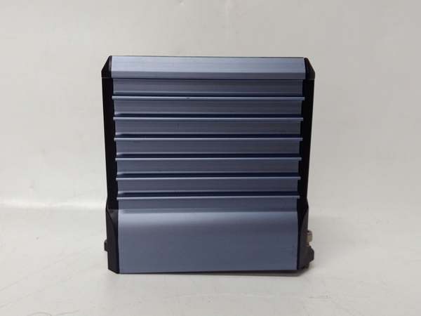
Hardware Architecture & Under-the-Hood Logic
This pulse input module contains isolated 32-bit counters, configurable input filters, and a microprocessor for signal processing and diagnostics. Each channel has independent isolation barriers and counter circuitry, preventing ground potential differences and signal noise from affecting accuracy. The module communicates over the Foxboro fieldbus to the I/A Series control system.
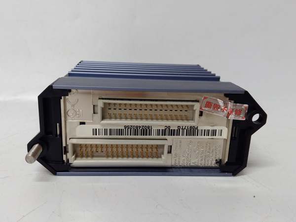
- Pulse signals from field devices enter through the terminal block and pass through configurable RC input filters.
- Filter circuits suppress noise and debounce pulse edges based on user settings (0.01-10 ms).
- Isolated 32-bit counters increment on each valid pulse edge (rising, falling, or both, depending on configuration).
- Counter values are processed by the microprocessor based on selected mode: totalize, frequency, rate, or pulse width.
- Processed values (total counts, frequency in Hz, flow rate, position) are transmitted over the fieldbus to the I/A Series controller.
- Diagnostics circuits monitor signal integrity, open circuits, and wiring faults per channel.
- Watchdog timers monitor microprocessor health, triggering fault alerts if system integrity is compromised.
FOXBORO FBM215
Field Service Pitfalls: What Rookies Get Wrong
Incorrect Counter Mode ConfigurationRookies configure the wrong counter mode for the application (e.g., frequency instead of totalize). Process values are incorrect because the module processes pulses differently than required, causing flow rate errors or batch count discrepancies.
- Field Rule: Verify the required measurement type before configuration. Use Totalize mode for batch counters and custody transfer, Frequency mode for tachometers, and Rate mode for flow metering with pulse-to-engineering unit conversion.
Improper Input Filter Settings on Noisy SignalsNew engineers set filter times too short on noisy pulse lines. Signal noise triggers false counts, causing inflated readings, while excessive filtering misses genuine pulses at high frequencies.
- Quick Fix: Adjust input filter based on signal quality. Use 0.1-0.5 ms for clean signals from proximity switches, 1-2 ms for flow meters, and 5-10 ms for noisy environments. Verify counter accuracy at both low and high pulse rates.
Exceeding Frequency Range LimitsTechnicians connect high-speed encoders exceeding the module’s 10 kHz (20 kHz max) frequency capability. Missed pulses occur, causing inaccurate position or speed data. The module may reset unexpectedly from signal overflow.
- Field Rule: Verify maximum pulse rate from field devices stays within the module’s frequency range. For high-speed encoders, use dedicated counter modules with higher frequency capability or consider signal dividers to reduce pulse rate.
Poor Shielding on Long Pulse Cable RunsRookies run unshielded pulse cables over long distances near high-voltage equipment. Electrical noise corrupts pulse edges, causing false counts or missed pulses, especially at lower signal levels.
- Field Rule: Use twisted pair shielded cable for all pulse signal wiring. Ground shields at the module end only to prevent ground loops. Maintain separation from power cables (minimum 12 inches / 30 cm). For runs over 100 meters, install signal conditioners or line drivers.
Please note: The listed price is for reference only and is not binding. Final pricing and terms are subject to negotiation based on current market conditions and availability.


