
Description
Hard-Numbers: Technical Specifications
- Series: I/A Series Fieldbus
- Input Channels: 16 (independent, isolated)
- Input Voltage Range: 24V DC (nominal), 18-32V DC range
- Input Current: 5-7 mA per channel
- Response Time: 10 ms typical (configurable 1-100 ms)
- Filter Time: Configurable 0-255 ms
- Isolation Rating: 1500 VDC channel-to-channel, 1500 VDC channel-to-system
- Wiring Type: 2-wire (sourcing or sinking)
- Power Supply: 24V DC fieldbus power
- Power Draw: 8W typical
- Operating Temperature: -40°C to +70°C
- Storage Temperature: -40°C to +85°C
- Relative Humidity: 5% to 95% non-condensing
- Certifications: AC/DC Voltage and Current, 30 V, AC/DC 15 VA, 30 V
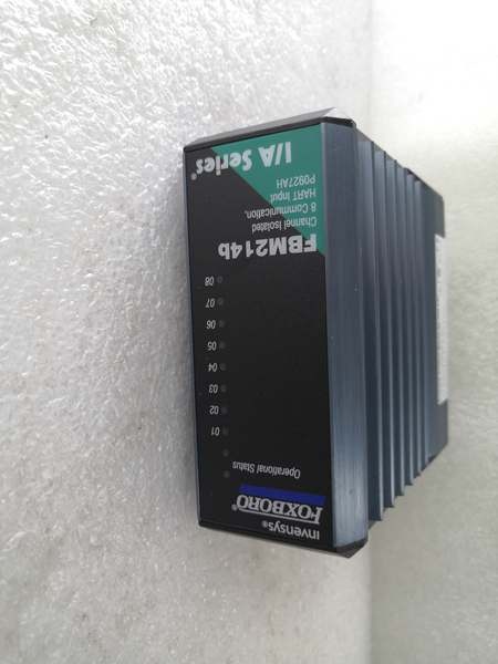
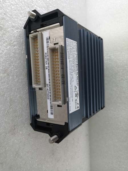
FBM214B
The Real-World Problem It Solves
Digital inputs suffer from contact bounce, voltage transients, and ground loops in industrial environments. Non-isolated input cards let noise and stray voltages corrupt logic states, causing false triggering and unreliable status monitoring. The FBM214B provides per-channel isolation eliminating ground loops, configurable input filters suppressing contact bounce, and digital diagnostics for reliable discrete input monitoring across all 16 channels.
Where you’ll typically find it:
- Limit switch monitoring in packaging machinery
- Push button and selector switch status indication
- Solenoid valve position feedback
- Motor starter and contactor status monitoring
Bottom line: It delivers reliable, isolated digital input for critical discrete status monitoring.
Hardware Architecture & Under-the-Hood Logic
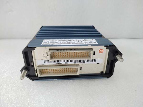
This digital input module contains isolated optocouplers, configurable input filters, and a microprocessor for signal processing and diagnostics. Each channel has independent isolation barriers, preventing ground potential differences and voltage transients between field devices from affecting logic states. The module communicates over the Foxboro fieldbus to the I/A Series control system.
- Field device signals (24V DC) enter through the terminal block and pass through RC input filters.
- Configurable filter circuits suppress contact bounce and voltage transients based on user settings.
- Optocouplers provide electrical isolation between field circuits and internal logic per channel.
- Isolated digital signals are digitized by the microprocessor for processing and fieldbus communication.
- Diagnostics circuits monitor input voltage levels, open circuits, short circuits, and wiring faults per channel.
- Watchdog timers monitor microprocessor health, triggering fault alerts if system integrity is compromised.
- Processed input states and diagnostic data are transmitted over the fieldbus to the I/A Series controller.
FBM214B
Field Service Pitfalls: What Rookies Get Wrong
Incorrect Wiring Configuration (Sourcing vs. Sinking)Rookies wire inputs incorrectly for the field device type, mixing sourcing and sinking configurations. Channels don’t respond properly or read incorrect logic states because the current flow direction doesn’t match the module’s configuration.
- Field Rule: Verify field device output type (sourcing or sinking) before wiring. Configure module inputs accordingly. Test each channel individually before putting the system into service.
Improper Input Filter SettingsNew engineers set filter times too short on vibrating machinery or too long on fast-acting devices. Short filters cause false triggering from contact bounce, while long filters delay response and miss rapid state changes.
- Quick Fix: Set filter times based on application requirements. Use 10-20 ms for standard switches, 50-100 ms for vibrating machinery, and 1-5 ms for high-speed pulse counting. Verify response time matches process requirements.
Ignoring Input Voltage LevelsTechnicians don’t verify input voltage range matches module specifications. Applying voltages outside 18-32V DC range can damage optocouplers or cause erratic readings. Low voltages cause unreliable state detection.
- Field Rule: Measure input voltage at the terminal block during commissioning. Verify voltage is within 18-32V DC range under all operating conditions. Use external power supplies if field voltages are insufficient.
Poor Grounding on Multiple Input SourcesRookies connect multiple field devices to different ground references without considering isolation limits. Ground potential differences cause circulating currents through optocouplers, corrupting logic states and causing false alarms.
- Field Rule: For isolated inputs, maintain separate ground references for each device if ground potentials differ significantly. Use external isolation barriers if ground potential differences exceed 30V. Never create ground loops through isolated channels.
Please note: The listed price is for reference only and is not binding. Final pricing and terms are subject to negotiation based on current market conditions and availability.


