

Description
Hard-Numbers: Technical Specifications
- Series: I/A Series Fieldbus
- Output Channels: 8 (independent, isolated)
- Output Range: 4-20mA (1-21mA extended range)
- Accuracy: ±0.1% of span
- Resolution: 16-bit
- Load Resistance: 0-750Ω per channel
- Isolation Rating: 1500 VDC channel-to-channel, 1500 VDC channel-to-system
- HART Support: Bell 202 FSK, 1200 bps (per channel)
- Power Supply: 24V DC fieldbus power
- Power Draw: 15W typical
- Operating Temperature: -40°C to +70°C
- Storage Temperature: -40°C to +85°C
- Relative Humidity: 5% to 95% non-condensing
- Certifications: CE, UL, CSA, FM, ATEX, IECEx
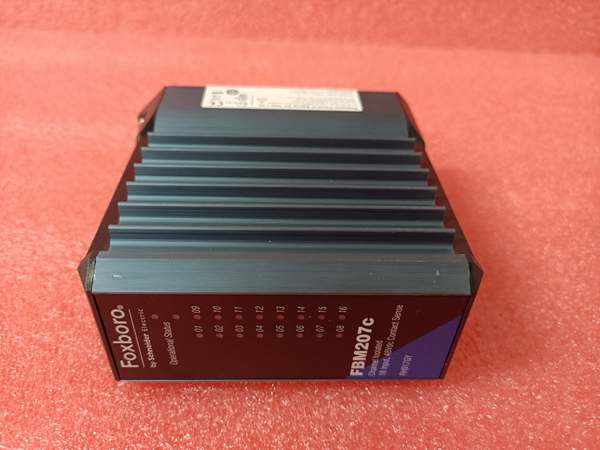
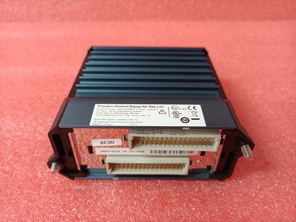
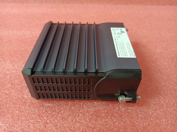
Foxboro FBM207C
The Real-World Problem It Solves
Control valves and actuators need precise analog current signals for accurate positioning. Non-isolated output modules let ground loops and stray currents corrupt output signals, causing valve position errors and process instability. The FBM207C delivers isolated 4-20mA outputs with HART support, ensuring precise analog control while enabling remote device diagnostics and configuration through HART communication.
Where you’ll typically find it:
- Control valve positioning in chemical process plants
- Flow control loop outputs in refinery operations
- Actuator control in power generation and utility systems
- Variable speed drive setpoints in industrial processes
Bottom line: It provides reliable, isolated analog output for precision process control.
Hardware Architecture & Under-the-Hood Logic
This analog output module contains isolated D/A converters, HART modem circuitry, and a microprocessor for signal processing and diagnostics. Each channel has independent isolation barriers, preventing ground potential differences between field devices from affecting output signals. The module communicates over the Foxboro fieldbus to the I/A Series control system.
- The I/A Series controller sends output setpoints to the FBM207C via the fieldbus.
- The microprocessor validates setpoints and routes them to the appropriate channel processors.
- Isolated D/A converters convert digital setpoints to analog current signals (4-20mA).
- Output drivers deliver current to field devices through terminal connections.
- HART modems superimpose digital communication on the 4-20mA signal for device diagnostics and configuration.
- Diagnostics circuits monitor output current, open circuits, short circuits, and wiring faults per channel.
- Watchdog timers monitor microprocessor health, triggering fault alerts and driving outputs to safe state on failure.
Foxboro FBM207C
Field Service Pitfalls: What Rookies Get Wrong
Exceeding Load Resistance LimitsRookies wire multiple control valves in series or add excessive resistance in the loop. Total resistance exceeds 750Ω, causing output voltage saturation and incorrect valve positioning. The valve may not open fully or respond erratically.
- Field Rule: Calculate total loop resistance including valve positioner input resistance and cable resistance. Keep total under 750Ω per channel. For long cable runs, use larger gauge wire to minimize resistance.
Improper HART Resistor InstallationTechnicians omit the 250Ω HART resistor or install it in the wrong location. HART communication fails because the minimum loop resistance for FSK modulation isn’t met, losing device diagnostics and configuration capability.
- Quick Fix: Install a 250Ω resistor at the output terminal or within the field device loop. Verify the resistor is installed correctly and that total loop resistance meets HART requirements (minimum 250Ω).
Mixed Grounding on Isolated OutputsNew engineers ground the loop return side at both the module and the field device. Ground potential differences create circulating currents through the isolation barrier, corrupting output signals and causing valve position errors.
- Field Rule: For isolated outputs, ground the loop return at the module end only. If the field device requires grounding, use an external isolator or verify grounding potentials are within 1V. Never create ground loops through isolated channels.
Ignoring Diagnostic Alarms During CommissioningTechnicians ignore initial diagnostic alarms during startup, assuming they’re temporary wiring issues. Unaddressed diagnostics indicate real problems like open circuits or shorted loops that cause process upsets later.
- Field Rule: Address all diagnostic alarms immediately during commissioning using the I/A Series diagnostic tools. Verify each channel operates correctly before putting the loop into service. Document alarm conditions and resolutions for future reference.
Please note: The listed price is for reference only and is not binding. Final pricing and terms are subject to negotiation based on current market conditions and availability.


