
Description
Hard-Numbers: Technical Specifications
- Series: 95DSS Series
- Scanner Inputs: 2 (supports UV or IR scanners)
- Output Relay: 10A at 250V AC (fuel valve safety shutoff)
- Alarm Relay: 5A at 250V AC
- Power Supply: 120/240V AC, 50/60Hz
- Power Draw: 15W typical
- Operating Temperature: -20°C to +60°C
- Storage Temperature: -40°C to +85°C
- Relative Humidity: 5% to 95% non-condensing
- Enclosure: NEMA 4X (IP66) indoor/outdoor rated
- Certifications: UL, FM, CSA, CE, ATEX, IECEx
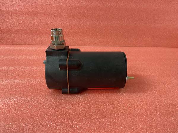
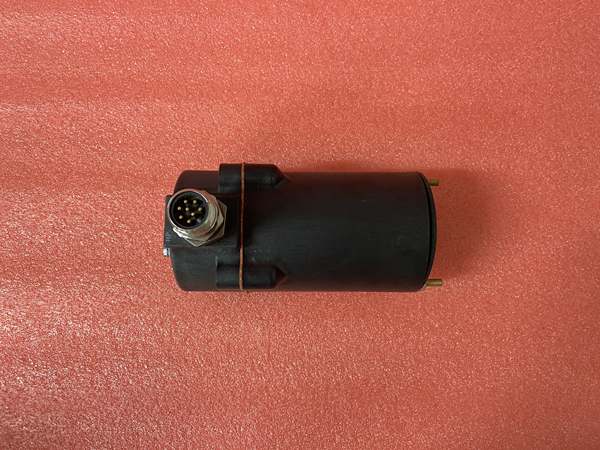
Fireye 85UVF1-1QDK3
The Real-World Problem It Solves
Burners need reliable flame detection and safety shutdown to prevent explosions and fuel damage. Single-scanner systems can fail to detect flame loss, creating dangerous conditions. The 95DSS2-1CEX uses dual scanner input with cross-checking logic, ensuring reliable flame detection while providing automatic safety shutdown on fault or flame loss.
Where you’ll typically find it:
- Industrial burners in refineries and petrochemical plants
- Power plant boilers and steam generators
- Process heaters in chemical plants
- Large commercial boilers and heaters
Bottom line: It provides redundant flame monitoring and safe burner operation for high-risk applications.
Hardware Architecture & Under-the-Hood Logic
The 95DSS2-1CEX contains a microprocessor-based controller that manages burner sequences and monitors two independent flame scanner inputs. The controller includes multiple output relays for fuel valve control, alarm outputs, and status indication. Integrated diagnostics monitor scanner health, wiring integrity, and system faults.
- Two independent flame scanners connect to the controller via shielded cables.
- The microprocessor continuously monitors both scanner signals for flame presence.
- Cross-checking logic compares scanner outputs to detect discrepancies or inconsistent signals.
- If both scanners agree on flame presence, the fuel valve relay closes, allowing fuel flow.
- If either scanner detects flame loss or faults, the fuel valve relay opens immediately, cutting fuel supply.
- Alarm relays indicate flame status, system faults, or diagnostic errors to the control system.
- Watchdog timers monitor microprocessor health, triggering safe shutdown on processor fault.
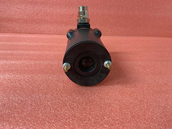
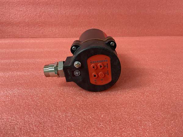
Fireye 85UVF1-1QDK3
Field Service Pitfalls: What Rookies Get Wrong
Incorrect Scanner AssignmentRookies wire scanners to the wrong inputs or don’t configure the controller for the correct scanner types (UV vs. IR). This causes false flame signals or missed flame detection, leading to burner trips or unsafe operation.
- Field Rule: Verify scanner type matches the configuration in the controller setup menu. Label both scanners and their corresponding inputs to prevent confusion during troubleshooting.
Ignoring Flame Signal Strength SettingsNew technicians don’t adjust flame signal strength thresholds after installation. Weak scanner signals cause nuisance trips during load changes, while excessive sensitivity leads to false flame signals from background radiation.
- Quick Fix: Perform flame signal strength calibration during commissioning using the controller setup menu. Set signal strength within the recommended range for the specific burner type and fuel. Recheck settings after any burner or scanner replacement.
Poor Grounding Causing Intermittent FaultsTechnicians connect the controller without proper grounding to the burner structure or control cabinet. Electrical noise from nearby motors or VFDs causes erratic flame signals and nuisance trips.
- Field Rule: Bond the controller chassis to the burner structure or control cabinet using a 10mm² (6 AWG) ground strap. Verify grounding resistance is less than 0.1 ohm. Use shielded scanner cables and terminate shields only at the controller end.
Skipping Pre-Purge ValidationRookies don’t validate pre-purge timing or air flow switches before putting the burner into service. The controller fails during startup or trips due to interlock violations, causing unnecessary downtime.
- Field Rule: Test all interlock switches (air flow, gas pressure, damper position) before burner startup. Verify pre-purge time meets local codes and manufacturer recommendations. Document all interlock test results for safety records.
Please note: The listed price is for reference only and is not binding. Final pricing and terms are subject to negotiation based on current market conditions and availability.


