
Description
Hard-Numbers: Technical Specifications
-
Detection Method: Ultraviolet (UV), 185-260 nm via UV gas-filled tube
-
Fiber-Optic Cable: 3 ft (0.9 m) armored stainless steel sheathing, silica core, 0.25″ OD, factory-terminated to sensor head and electronics housing
-
Operating Temperature (Electronics): -40°F to +150°F (-40°C to +65°C)
-
Operating Temperature (Sensor Head): Up to +250°F (+121°C) continuous at lens face; +300°F (+149°C) intermittent
-
Supply Voltage: 24 VDC ±10% (standard), reverse polarity protected
-
Power Draw: 3.5 W max @ 24 VDC; 150 mA typical
-
Analog Output: 4-20 mA, flame signal strength, 500 ohm max load, isolated
-
Digital Outputs: Two SPDT relays (Flame On, Fault), 5A @ 250 VAC, 30 VDC
-
Response Time: Selectable 1, 2, 3, 4, or 6 seconds flame failure; default 3 seconds
-
Communication: RS-485 Modbus RTU, 9600-115200 baud, configurable node address
-
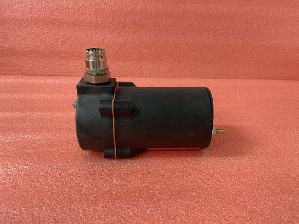
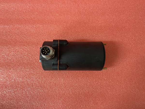
Electrical Connection: 8-pin quick-disconnect (QD) circular connector, MIL-spec compatible
-
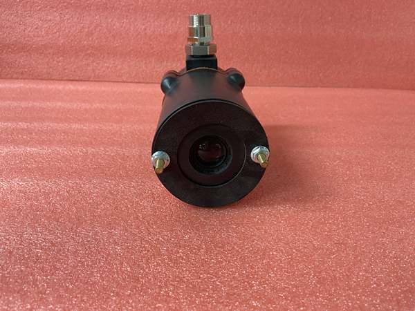
Sensor Head: 1″ NPT external thread, 3/4″ NPT internal option, quartz lens, UV tube field-replaceable
-
Enclosure: Die-cast aluminum, NEMA 4/4X, two 3/4″ NPT conduit entries
-
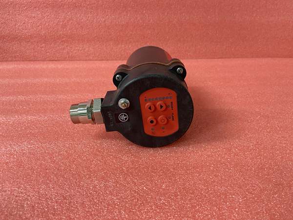
LED Indicators: Flame signal strength (4-bar), Relay status, Fault/Alarm, Power

FIREYE 85UVF1-1QDK3
The Real-World Problem It Solves
Standard 6 ft fiber-optic scanners leave you with 4 feet of coiled cable stuffed into a 18-inch burner compartment. That coil gets hot, vibrates against sharp edges, and eventually fatigues. The K3 variant gives you exactly 3 ft—enough to drop from the electronics housing (mounted on the burner windbox exterior) straight to the sight pipe without slack. Less cable, fewer failure points, cleaner routing.
Where you’ll typically find it:
-
Package watertube boilers with tight burner front clearances and multiple scanners crowded together
-
Small HRSG duct burners where the sight pipe is within arm’s reach of the scanner mounting bracket
-
OEM burner skids shipped with pre-cut fiber lengths to match the shop drawing—no field trimming needed
Bottom line: It eliminates the “what do I do with all this extra cable?” problem that turns neat installations into maintenance headaches.
Hardware Architecture & Under-the-Hood Logic
The 85UVF1-1QDK3 uses the same Phoenix platform as its longer-cable siblings, but the K3 suffix locks you into a fixed 3 ft optical path. The sensor head is passive—just a UV tube and lens coupling. All intelligence lives in the main housing: microprocessor, relay drivers, 4-20 mA loop, and Modbus transceiver. The QD connector means you can swap the entire scanner in 90 seconds without touching terminal screws.
Internal signal flow:
-
UV Detection: Gas-filled UV tube ionizes on 185-260 nm photon strike; generates discrete electrical pulses proportional to flame intensity
-
Signal Conversion: Tube pulses feed high-impedance amplifier; noise filtering removes ignition spark interference
-
Microprocessor Logic: Counts pulses per second, compares against programmable threshold (20-200 Hz typical); auto-drifts baseline to compensate for tube aging
-
Relay Drive: Flame On relay energizes after programmed “flame proven” delay (0.5-10 sec); de-energizes on flame failure or self-check fault
-
Diagnostics Loop: Continuous UV tube health check, fiber break detection (loss of signal continuity), supply voltage monitoring; Fault relay opens, 4-20 mA drops to 0 mA, Modbus register flags specific fault code
FIREYE 85UVF1-1QDK3
Field Service Pitfalls: What Rookies Get Wrong
Assuming All 85UVF1 Models Have the Same Cable Length You grab a spare from stores labeled “85UVF1-1QD” and show up to replace a -1QDK3. The 6 ft cable won’t fit in the 3 ft routed space without a loop that hits 400°F ductwork. Now you’re making emergency calls for the right part number while the unit sits offline.
-
Field Rule: Verify the suffix. K3 = 3 ft, K6 = 6 ft, K12 = 12 ft. The “K” denotes the fiber kit length. Stock the exact variant your site standardized on, or carry a union coupling and extra conduit to route longer cable properly.
Forcing the QD Connector Alignment The 8-pin quick-disconnect has a keyway. Muscle it 180 degrees out and you’ll bend pins, crack the insulator, or create an intermittent that shows up three months later as random flame failures. I’ve seen techs use channel locks “to make sure it’s tight.”
-
Quick Fix: Line up the index notch by feel—it’s clocked at 12 o’clock. Hand-tighten the threaded collar until it seats, then snug 1/4 turn with fingers only. If you need tools to get it tight, the pins are misaligned. Pull it, inspect with a flashlight, try again. Carry spare male and female QD bodies in your kit; they’re cheaper than a night callout.
Ignoring the Fiber Bend Radius at the Sensor Head The K3 cable is short, so techs sharp-angle it out of the sensor head to make the run fit. That 90-degree kink right at the strain relief fractures the silica after six months of thermal cycling. You get “low flame signal” alarms that clear when you tap the head.
-
Field Rule: Maintain 3″ minimum bend radius from the sensor head housing—use a 45-degree conduit fitting or a sweeping bend support. Never let the armor touch the burner front plate directly; use the supplied insulating grommet. If the flame signal drops 20% when you heat-cycle the burner, you’ve got a micro-fracture. Replace the scanner; the fiber isn’t field-repairable.


