
Description
Hard-Numbers: Technical Specifications
- Detector Type: UV (Ultraviolet) flame detector
- Wavelength Range: 190-270 nm
- Field of View: 70° cone angle
- Response Time: 0.1 seconds typical
- Operating Temperature: -40°C to +85°C
- Storage Temperature: -40°C to +85°C
- Power Supply: 18-30V DC (nominal 24V DC)
- Power Draw: 50mA typical
- Output: Relay contact output (Form C, 5A at 240V AC)
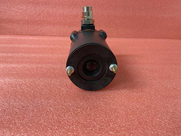
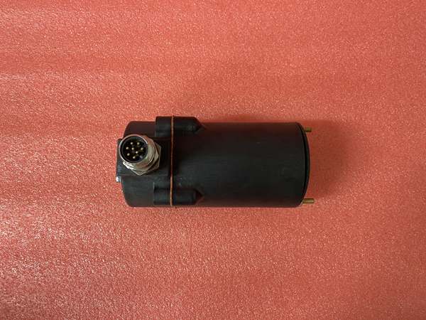
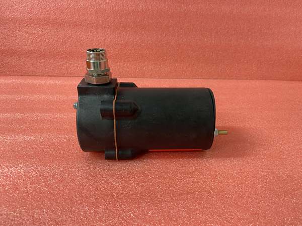
- Mounting: M18 threaded probe with stainless steel housing
- Certifications: ATEX, IECEx, FM, CSA, CE
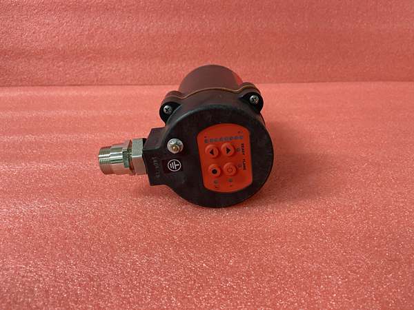
Fireye 85UVF1-1QDK3
The Real-World Problem It Solves
Industrial burners need reliable flame detection to ensure safe operation and prevent explosions. Old thermocouple-based systems are slow and prone to false readings from ambient heat. The 85UVF1-1QDK3 uses UV detection to identify flame presence quickly and accurately, responding to flame loss in less than 0.1 seconds while ignoring ambient radiation and false triggers.
Where you’ll typically find it:
- Industrial burners in refineries and petrochemical plants
- Power plant boilers and steam generators
- Process heaters in chemical plants
- Waste incineration facilities
Bottom line: It provides fast, reliable flame detection for industrial combustion systems.
Hardware Architecture & Under-the-Hood Logic
This UV flame scanner contains a UV-sensitive phototube that detects UV radiation from flames. The phototube generates a current signal when exposed to UV radiation, which is processed by the internal electronics module. The unit includes an output relay that changes state when a flame is detected or lost.
- The UV phototube converts UV radiation from a flame into an electrical current signal.
- The internal electronics module amplifies and filters the current signal to remove noise and interference.
- The processor compares the filtered signal to a threshold level to determine flame presence.
- If the signal exceeds the threshold, the relay contact changes state (closes for flame detected, opens for flame lost).
- The unit includes diagnostics for phototube health, power supply status, and signal integrity.
- Temperature-compensated components ensure consistent performance across the operating temperature range.
- EMI shielding protects the electronics from interference from nearby motors and VFDs.
Fireye 85UVF1-1QDK3
Field Service Pitfalls: What Rookies Get Wrong
Installing the Scanner in Incorrect PositionRookies install the UV scanner outside the recommended detection zone or at the wrong angle. This causes missed flame detection, leading to unnecessary shutdowns or dangerous burner operation with no flame monitoring.
- Field Rule: Install the scanner at the recommended distance and angle specified in the installation manual. The scanner’s field of view should directly cover the primary flame zone of the burner. Perform a flame response test to verify proper detection.
Ignoring Phototube Aging and CalibrationNew technicians don’t perform regular phototube calibration or replacement. UV phototubes degrade over time, reducing sensitivity and causing false triggers or missed flame detection.
- Quick Fix: Perform annual calibration using a UV calibration source to verify detection sensitivity. Replace phototubes every 2-3 years depending on usage. Keep spare phototubes on hand for emergency replacements.
Poor Grounding Causing Electrical InterferenceTechnicians connect the scanner without proper grounding to the burner or control cabinet. Electrical noise from nearby motors, VFDs, or power lines causes false triggers or missed flame detection, leading to unpredictable burner operation.
- Field Rule: Bond the scanner housing to the burner or control cabinet using a 6mm² (4 AWG) ground strap. Verify grounding resistance is less than 1 ohm. Use shielded signal cables and ground shields only at the control cabinet end to prevent ground loops.
Overlooking Environmental ConditionsRookies don’t account for environmental factors such as high humidity, corrosive gases, or soot buildup on the scanner window. Humidity causes condensation on the window, while corrosive gases can damage the phototube over time, reducing detection accuracy.
- Field Rule: Install scanner window protectors in high-humidity or corrosive environments. Clean the scanner window regularly to remove soot buildup. Replace protective windows if they become scratched or damaged.
Please note: The listed price is for reference only and is not binding. Final pricing and terms are subject to negotiation based on current market conditions and availability.


