
Description
Hard-Numbers: Technical Specifications
-
Detection Method: Ultraviolet (UV), 185-260 nm via UV tube sensor
-
Fiber-Optic Cable: 3 ft, 6 ft, or 12 ft lengths; stainless steel sheathing with silica core; 0.25″ OD
-
Operating Temperature (Electronics): -40°F to +150°F (-40°C to +65°C)
-
Operating Temperature (Sensor Head): Up to +250°F (+121°C) continuous at lens face
-
Supply Voltage: 24 VDC ±10% (standard), 120 VAC option available (-1 model suffix)
-
Power Draw: 3.5 W max @ 24 VDC
-
Analog Output: 4-20 mA flame signal strength (source or sink configurable)
-
Digital Outputs: Two SPDT relays (Flame On, Fault/Alarm), 5A @ 250 VAC
-
Response Time: Adjustable 1-6 seconds flame failure (default 3 seconds)
-
Communication: RS-485 Modbus RTU for remote monitoring/setup
-
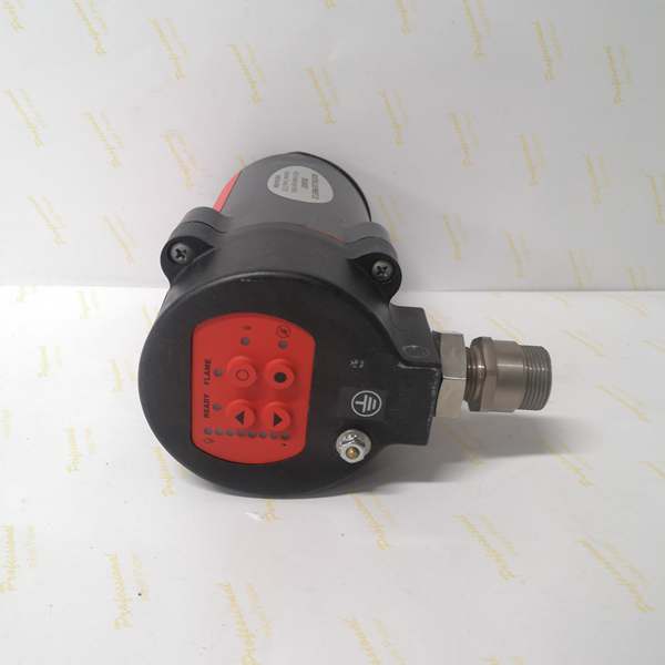
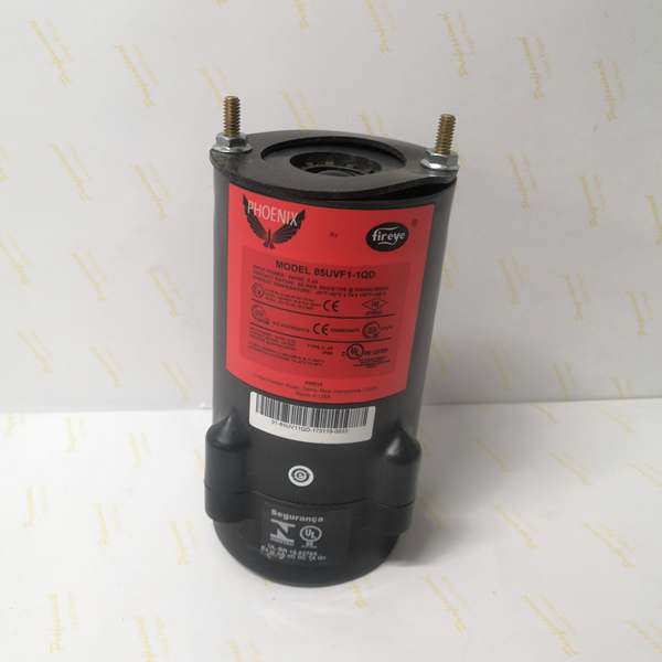
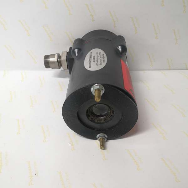
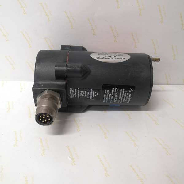
Enclosure: Die-cast aluminum, NEMA 4/4X, two 3/4″ NPT entries
-
Electrical Connection: 8-pin quick-disconnect (QD) or terminal block (-1 version)
-
Sensor Head: 1″ NPT mounting, quartz lens, field-replaceable UV tube

Fireye 85UVF1-1QD
The Real-World Problem It Solves
Conventional UV scanners die young when you mount them on a 2000°F boiler front or a gas turbine plenum. The 85UVF1-1QD splits the difference—fiber-optic cable carries the UV signal from the hot zone to the electronics sitting in a junction box 12 feet away. You get the reliability of remote mounting without the drift and alignment headaches of old-school UV tubes on mullion mounts.
Where you’ll typically find it:
-
HRSG duct burners where ambient hits 180°F+ and vibration from forced-draft fans cracks solder joints
-
Gas turbine combustor cans needing flame detection inside the can, not just sighting through a window
-
Refinery process heaters with multiple burners where electronics must live outside the firebox arch
Bottom line: It keeps the brains cool and the sensor hot-side, eliminating thermal failures that send you climbing scaffolding at 2 AM.
Hardware Architecture & Under-the-Hood Logic
The 85UVF1-1QD is a distributed system in one part number. The sensor head contains only the UV-sensitive gas-filled tube and fiber coupler—no active electronics. The main housing holds the microprocessor, relay drivers, and power supply. Fiber carries UV photons, not electrical signals, so you get immunity to EMI and ground loops.
Internal signal flow:
-
UV Conversion: Gas-filled UV tube ionizes when 185-260 nm radiation hits it; each photon event generates a discrete pulse
-
Fiber Transmission: UV pulses travel through silica fiber to the main housing; stainless armor prevents kinking and heat damage
-
Pulse Processing: Microprocessor counts pulses per second (frequency = flame intensity); auto-compensates for tube aging via baseline tracking
-
Relay Logic: Flame On relay energizes when pulse count exceeds threshold for programmed “on” delay; drops on flame failure or self-check fault
-
Self-Diagnostics: Continuous monitoring of UV tube health, fiber integrity (break detection), and internal power supply; Fault relay opens on any anomaly
Fireye 85UVF1-1QD
Field Service Pitfalls: What Rookies Get Wrong
Kinking the Fiber-Optic Cable During Install That stainless braid looks tough, but bend it tighter than a 3″ radius and you’ll fracture the silica core. No UV gets through, scanner reads “no flame” even with a roaring fire. I’ve seen techs route it like Romex around sharp conduit edges.
-
Field Rule: Treat it like coax—minimum 6″ bend radius, support every 18″, no tension on the sensor head. If the flame signal drops when you wiggle the cable, you’ve got a break. Replace the fiber assembly; don’t try to splice it.
Ignoring the 4-20 mA Loop Loading The analog output drives flame strength to your DCS, but it’s not a powered transmitter. Exceed 500 ohms loop resistance and the current sags, your control room sees a weak flame that isn’t real. Guys chase burner tuning when it’s a wiring issue.
-
Quick Fix: Calculate total loop resistance—cable run plus DCS input card. Keep it under 500 ohms at 24 VDC. If you need longer runs, use the RS-485 Modbus output instead; it’s digital and doesn’t care about distance under 4000 feet.
Forgetting to Configure the Relay Logic Out of the box, the Flame On relay energizes on flame proven (fail-safe). But some BMS logic expects a “flame not proven” contact to open on good flame. You power it up, see 4-20 mA, but the safety PLC won’t permit light-off because the relay’s wired backwards for your logic.
-
Field Rule: Check the dip switches or software config before you leave the ground. Fireye’s “Phoenix” software (or front-panel buttons) lets you invert relay logic. Test both relays with actual flame—verify NC/NO states match your cause-and-effect matrix. Document the settings on the inside of the enclosure cover.


