
Description
Hard-Numbers: Technical Specifications
- Series: βi (Beta i Series)
- Type: Spindle Amplifier Module
- Continuous Power: 6kW
- Peak Power: 9kW
- Continuous Current: 18A
- Peak Current: 28A
- Input Voltage: 200-240V AC, 3-phase
- DC Bus Voltage: 300V nominal
- Max Motor Speed: 8000-12000 RPM (motor dependent)
- Power Draw: 8kVA typical
- Operating Temperature: 0°C to +55°C
- Storage Temperature: -20°C to +60°C
- Relative Humidity: 10% to 90% non-condensing
- Certifications: CE, UL, CSA, RoHS
Fanuc A06B-6096-H104
The Real-World Problem It Solves
Small CNC machines need efficient spindle control without taking up excessive cabinet space. Older analog drives lack precision and diagnostics, making troubleshooting a guessing game. The A06B-6252-H060 delivers compact, digital spindle control with smooth torque output, ensuring stable spindle speeds under load while protecting both motor and amplifier from overload conditions.
Where you’ll typically find it:
- Small CNC turning centers and lathes
- Compact CNC machining centers
- High-speed CNC routers
- Woodworking and plastics CNC machines
Bottom line: It provides efficient, reliable spindle control for small to medium-power CNC applications.
Hardware Architecture & Under-the-Hood Logic
This βi spindle amplifier integrates a 3-phase AC rectifier, DC bus, and IGBT inverter into a compact module. A DSP-based vector controller calculates stator current vectors for precise speed and torque control. Encoder feedback from the spindle motor enables closed-loop speed control and spindle orientation functions.
- 3-phase AC input power enters the amplifier and is rectified to DC bus voltage (approx. 300V DC).
- DC bus capacitors store energy and smooth voltage fluctuations during acceleration and deceleration.
- The vector controller DSP receives speed commands from the CNC and calculates required stator current vectors based on motor speed and load.
- IGBT inverter converts DC bus voltage to variable-frequency 3-phase AC for the spindle motor.
- Spindle encoder feedback returns real-time speed and position data to the amplifier.
- The DSP adjusts inverter output in real-time to maintain precise speed control under varying load.
- Protection circuits monitor overcurrent, overvoltage, overtemperature, and encoder status, triggering safe shutdowns with specific fault codes.
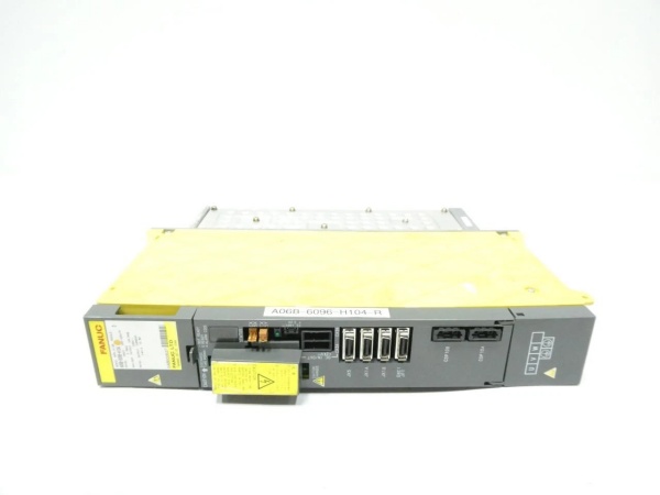
Fanuc A06B-6096-H104
Field Service Pitfalls: What Rookies Get Wrong
Incorrect Motor Parameter SetupNew engineers replace the amplifier without restoring motor parameters, assuming they are stored in the CNC. The spindle runs poorly, hunts, or stalls because the amplifier doesn’t match the motor characteristics.
- Field Rule: Back up all motor parameters from the old amplifier before replacement. After installation, restore parameters including motor pole count, rated speed, and torque limits.
Poor Grounding Causing Spindle NoiseTechnicians connect the spindle amplifier without proper grounding to the machine frame. Electrical noise from nearby motors or VFDs causes spindle speed fluctuations and poor surface finish.
- Field Rule: Bond the amplifier chassis to the machine frame using 4mm² (12 AWG) ground strap. Verify grounding resistance is less than 1 ohm. Use shielded motor cables with ground connections at both ends for high-power applications.
Overlooking Dynamic Braking RequirementsRookies skip dynamic brake resistor installation for small spindles, assuming regeneration is minimal. During rapid deceleration, the DC bus charges beyond safe limits, damaging capacitors or causing emergency 终止s.
- Quick Fix: Install a dynamic brake resistor sized for peak braking power (9kW for 3-5 seconds). Calculate braking energy based on spindle inertia and deceleration rate to ensure proper sizing.
Please note: The listed price is for reference only and is not binding. Final pricing and terms are subject to negotiation based on current market conditions and availability.


