
Description
Hard-Numbers: Technical Specifications
- Series: αi (Alpha i Series)
- Axis Control: 4 axes
- Continuous Current: 30A per axis
- Peak Current: 60A per axis
- Input Voltage: 200-240V AC, 3-phase
- DC Bus Voltage: 300V nominal (200V AC input)
- Total Power: 30kW typical
- Power Draw: 40kVA typical
- Operating Temperature: 0°C to +55°C
- Storage Temperature: -20°C to +60°C
- Relative Humidity: 10% to 90% non-condensing
- Certifications: CE, UL, CSA, RoHS
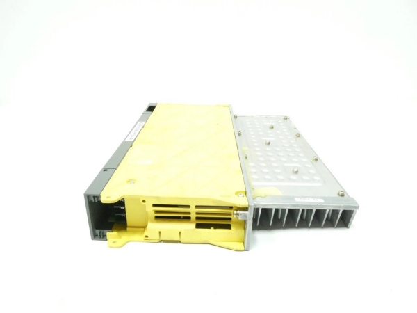
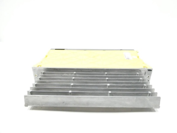
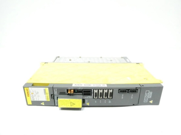
Fanuc A06B-6096-H104
The Real-World Problem It Solves
Multi-axis CNC machines need high-performance servo drives to handle synchronized motion across multiple axes. Old single-axis drives take up excessive cabinet space and increase wiring complexity. The A06B-6096-H104 integrates 4-axis servo control in a compact unit, saving cabinet space while providing precise multi-axis synchronization for complex machining operations.
Where you’ll typically find it:
- 5-axis CNC machining centers
- CNC lathes with live tooling
- Robotic work cells
- Multi-axis milling machines
Bottom line: It delivers synchronized multi-axis control while reducing cabinet footprint.
Hardware Architecture & Under-the-Hood Logic
This multi-axis amplifier integrates 4 independent servo drives into a single compact unit. A common 3-phase AC input feeds a shared DC bus, with each axis having its own IGBT inverter stage. A central DSP coordinates multi-axis synchronization, while individual axis processors handle independent current, speed, and position control.
- 3-phase AC input power enters the unit and is rectified to DC bus voltage.
- A shared DC bus with high-capacity capacitors provides energy storage and smoothing.
- Each axis has independent IGBT inverters converting DC power to variable-frequency 3-phase AC for servo motors.
- Encoder feedback from each motor returns position and velocity data to the corresponding axis processor.
- The central DSP synchronizes motion across all 4 axes using high-speed internal data buses.
- Integrated diagnostics monitor overcurrent, overvoltage, temperature, and encoder status per axis.
- Fault conditions trigger safe shutdowns with specific axis fault codes for quick troubleshooting.
Fanuc A06B-6096-H104
Field Service Pitfalls: What Rookies Get Wrong
Inadequate Cabinet Ventilation for Multi-Axis HeatRookies mount 4-axis amps in standard cabinets without increased cooling. This unit generates significant heat (approx. 30kW total), causing thermal alarms or component failure within hours. I’ve seen cabinets without proper ventilation run at 70°C—way over the 55°C limit.
- Field Rule: Calculate total heat dissipation (30kW for this unit). Install forced air cooling with filtered intake and exhaust fans sized for 2x heat capacity. Maintain internal cabinet temperature below 45°C.
Loose Multi-Axis DC Bus ConnectionsTechnicians don’t tighten DC bus connections properly for high-current multi-axis operation. Thermal cycling and vibration cause connections to loosen, leading to arcing, voltage spikes, and damage to multiple inverter stages simultaneously.
- Field Rule: Torque DC bus terminals to specification (10-12 N·m) using a calibrated torque wrench. Recheck torque after initial power-on and heat cycles. Lock terminals with thread locker for long-term reliability.
Ignoring Axis Synchronization SettingsNew engineers replace the amplifier without restoring multi-axis synchronization parameters. The machine loses positional accuracy across axes during synchronized motion, leading to scrapped parts and misalignment errors.
- Quick Fix: Back up all multi-axis synchronization parameters from the old unit. After replacement, restore parameters including SYNC_OFFSET, SYNC_MODE, and INTERPOLATION_RATE. Perform low-speed test cuts to verify positional accuracy.
Overlooking Grounding for Multi-Axis NoiseMulti-axis units generate more electrical noise than single-axis drives. Poor grounding causes cross-talk between axes, leading to encoder errors and axis following errors.
- Field Rule: Use separate ground buses for servo drive and control signals. Bond the amplifier chassis to the machine frame using 10mm² (6 AWG) ground strap. Use shielded encoder cables and terminate shields only at the cabinet end to prevent ground loops.
Please note: The listed price is for reference only and is not binding. Final pricing and terms are subject to negotiation based on current market conditions and availability.


