
Description
Hard-Numbers: Technical Specifications
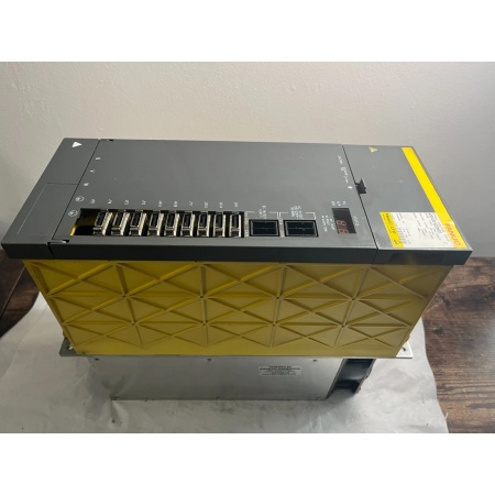
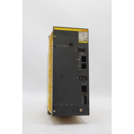
- Series: αi (Alpha i Series)
- Type: Spindle Amplifier Module
- Continuous Power: 37kW (50 HP approximate)
- Peak Power: 55kW (75 HP approximate)
- Continuous Current: 80A
- Peak Current: 120A
- Input Voltage: 200-240V AC, 3-phase
- Max Motor Speed: 6000-12000 RPM (motor dependent)
- Power Draw: 45kVA typical
- Operating Temperature: 0°C to +55°C
- Storage Temperature: -20°C to +60°C
- Relative Humidity: 10% to +90% non-condensing
- Certifications: CE, UL, CSA, RoHS
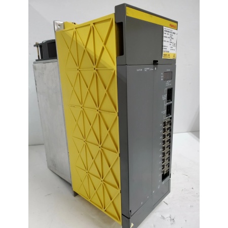
Fanuc A06B-6088-H222
The Real-World Problem It Solves
CNC main spindles need raw torque at low speeds for heavy cuts and consistent power at high speeds for finishing. Underpowered spindle drives stall during heavy roughing passes, causing tool breakage and scrapped workpieces. The A06B-6088-H222 delivers high-current output with vector control, providing smooth torque across the entire speed range and protecting both spindle motor and amplifier from overload conditions.
Where you’ll typically find it:
- CNC turning centers driving main spindles
- Vertical machining centers powering spindle motors
- Horizontal boring mills controlling boring spindles
- High-torque drilling machines
Bottom line: It delivers the power and control needed for demanding CNC spindle applications.
Hardware Architecture & Under-the-Hood Logic
This αi spindle amplifier contains a 3-phase AC input rectifier, DC bus with high-capacity capacitors, and IGBT inverter output stage. The module includes a DSP-based vector control system that regulates torque and speed based on feedback from spindle encoder or pulse coder. Integrated diagnostics monitor current, voltage, temperature, and spindle orientation.
- 3-phase AC input power enters the amplifier and is rectified to DC bus voltage (approx. 300V DC for 240V input).
- DC bus capacitors filter and store energy, providing stable DC voltage for the inverter stage.
- The DSP-based vector controller receives speed/torque commands from the CNC controller and calculates required stator current vectors.
- IGBT inverter converts DC bus voltage to variable-frequency 3-phase AC for the spindle motor.
- Spindle encoder or pulse coder feedback returns real-time speed and position data to the amplifier.
- The DSP adjusts inverter output in real-time based on feedback, maintaining precise speed control even under varying load.
- Protection circuits monitor overcurrent, overvoltage, overtemperature, and ground faults, triggering alarms and safe shutdowns.
Fanuc A06B-6088-H222
Field Service Pitfalls: What Rookies Get Wrong
Inadequate Dynamic Braking Resistor SizingRookies install the spindle amp without calculating braking energy. During rapid spindle deceleration, the DC bus overcharges and triggers overvoltage alarms, damaging the amplifier or causing emergency 终止s.
- Field Rule: Calculate braking energy based on spindle inertia and deceleration rate. Install a properly sized dynamic braking resistor if the application requires frequent rapid 终止s. Verify the resistor can handle peak power (typically 2-3x motor power for 3-5 seconds).
Ignoring Spindle Orientation ParametersNew engineers replace the amplifier without setting spindle orientation parameters. The spindle won’t 终止 at the correct position for tool changes, causing tool changer crashes and misalignment.
- Quick Fix: Back up spindle orientation parameters from the old amplifier. After replacement, restore parameters including ORIENT, ORIENT_DIR, and ORIENT_SPEED. Perform tool change test at low speed before production.
Poor Grounding Causing Spindle NoiseTechnicians connect the spindle amp without proper grounding. Electrical noise causes spindle speed fluctuations, encoder errors, and poor surface finish on workpieces.
- Field Rule: Bond the amplifier chassis to the machine frame using 10mm² (6 AWG) ground strap. Verify grounding resistance is less than 0.1 ohm for spindle drives. Shielded encoder cables must be grounded at the cabinet end only.
Overlooking Motor Lead Length CompensationTechnicians install long motor cables without compensating for voltage drop. The motor receives insufficient voltage, causing torque loss and overheating at high speeds.
- Field Rule: For motor leads over 20 meters, increase output voltage or use larger gauge cable. Verify voltage drop is less than 5% at full load. Install load reactors if cable length exceeds 30 meters to protect the amplifier from reflected wave damage.
Please note: The listed price is for reference only and is not binding. Final pricing and terms are subject to negotiation based on current market conditions and availability.


