
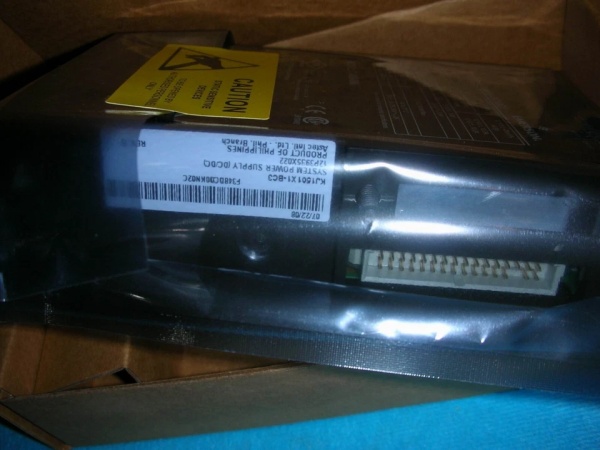
Description
Hard-Numbers: Technical Specifications
- Input Characteristics:
- Input Voltage Options: 12 VDC or 24 VDC (selectable via wiring)
- 12 VDC Input Range: -4% to +5% (11.5–12.6 VDC) at 14.8 A max
- 24 VDC Input Range: ±20% (19.2–28.8 VDC) at 6.1 A max
- Input Protection: Internally fused (non-replaceable), inrush current limiting
- Output Ratings (-40°C to +60°C) :
- 12 VDC Output: 13 A max (12 VDC input) or 8 A max (24 VDC input)
- 5.1 VDC Output: 2.0 A max
- 3.4 VDC Output: 2.0 A max
- Combined 5V/3.3V Output Power: 10 W total
- Output Ratings (60°C to +70°C with derating) :
- 12 VDC Output: 10 A max (12 VDC input) or 6 A max (24 VDC input)
- 5.1 VDC Output: 2.0 A max
- 3.4 VDC Output: 2.0 A max
- Protection Features:
- Overvoltage Protection: Output protected at 110% to 120% of nominal
- Input Protection: Internal fuse, soft-start inrush limiting
- Isolation: Galvanic isolation between system power and field power
- Environmental:
- Operating Temperature: -40°C to +60°C (full rating), 60°C to +70°C (derated)
- Storage Temperature: -40°C to +70°C
- Relative Humidity: 5% to 95% non-condensing
- Shock Resistance: 10 g, ½ sine wave, 11 ms
- Vibration Resistance: 1 mm peak-to-peak (5-16 Hz), 0.5 g (16-150 Hz)
- Airborne Contaminants: ISA-S71.04-1985 Class G3
- Physical:
- Weight: 0.5-1.0 kg (module only)
- Mounting: Plug-in to DeltaV power/controller carrier (2-wide or 4-wide slots)
- Certifications:
- Hazardous Area: FM Class 1 Div 2, Cenelec Zone 2 A/B/C/D T4, ATEX 3 G IIC T4 (Ex nC)
- Alarm Relay Parameters: Uo = 30 VDC, Io = 135 mA, Lo = 20 µH
- Global Approvals: CE, CSA, EMC compliant
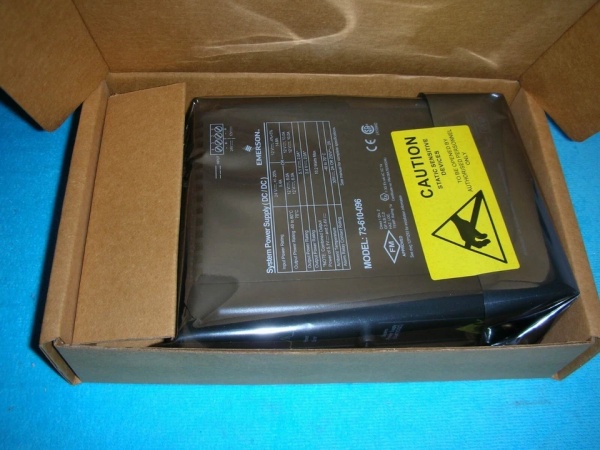
EMERSON VE5009
The Real-World Problem It Solves
Running legacy DeltaV systems required separate bulk power supplies: one for 24 VDC field power, another for 12 VDC I/O interface power, and a third for controller logic. That meant three power cabinets, triple the wiring, and no graceful failover. The VE5009 consolidates DC/DC conversion into a single module that takes either 12 or 24 VDC bulk power and generates all three regulated voltages (12V, 5V, 3.3V) needed for controllers and I/O cards. Its high-efficiency design eliminates the need for dedicated 12 VDC bulk supplies—you can power your entire DeltaV system from a standard 24 VDC plant distribution network. When paired with a redundant VE5009 module, you get hot-standby failover: if the primary bulk supply dies, the secondary takes over without controller reboot.
Where you’ll typically find it:
- Refinery control rooms powering DeltaV M-series controllers with redundant 24 VDC bulk supplies
- Pharmaceutical batch process skids where hazardous area (Zone 2) power distribution is required
- Chemical plant I/O cabinets needing 12 VDC LocalBus power for dense card installations
- Upgraded DeltaV systems replacing older CE5008 power supplies without rewiring bulk power
Bottom line: This is the DC/DC workhorse for modern DeltaV power architecture—consolidate your bulk supplies, gain redundant failover, and stay Zone 2 compliant with a single module.
Hardware Architecture & Under-the-Hood Logic
The VE5009 is a DC/DC converter module designed to plug into a DeltaV power/controller carrier alongside DeltaV controllers (M-series, C-series). Its job is to accept bulk DC power (12 or 24 VDC) and regulate it to the precise voltages needed by DeltaV electronics: 12 VDC for I/O interface cards (LocalBus), 5 VDC for legacy controller logic, and 3.3 VDC for modern controller processors. The module provides galvanic isolation between the messy plant power and the sensitive DeltaV electronics.
-
Bulk Power Input Stage: The VE5009 accepts bulk DC power through a 2-wire primary power connector (screw terminal or plug-in). You can feed it either 12 VDC or 24 VDC—the module auto-detects the input voltage and adjusts its DC/DC conversion topology accordingly. The 12 VDC input option is for legacy systems with existing 12 VDC bulk supplies; 24 VDC input is preferred for new installations because it reduces current draw on plant distribution (half the amps for the same power output). Input protection includes an internal non-replaceable fuse that blows on catastrophic overcurrent, soft-start circuitry that limits inrush current to 12 A (12 VDC input) or 20 A (24 VDC input) for the first 5 ms during power-up.
-
DC/DC Conversion Topology: The module uses high-efficiency switching converters (likely synchronous buck topology) to step down bulk voltage to regulated outputs. Efficiency isn’t explicitly stated in available specs, but Emerson claims “more efficient than CE5008” and markets it as reducing heat dissipation and bulk power requirements. The 12 VDC output is the workhorse—it powers the LocalBus that distributes 12 VDC to all I/O cards in the carrier. The 5 VDC and 3.3 VDC outputs are lower current (2 A each) and power the controller’s internal electronics—CPU memory, I/O buffers, and communication circuits.
-
LocalBus Distribution: The VE5009 connects to the power/controller carrier’s internal power bus, which distributes 12 VDC to all I/O interface cards via the LocalBus backplane. No external cabling needed—just plug the module into the carrier, and 12 VDC appears at every I/O card slot. The VE5009 can deliver up to 13 A at 12 VDC when fed from 12 VDC bulk power, or 8 A when fed from 24 VDC bulk power (at -40°C to +60°C). Above 60°C, you must derate: 10 A (12 VDC input) or 6 A (24 VDC input). Emerson’s docs state 8 A max from 24 VDC input is the typical horizontal I/O carrier rating—check your I/O load calculation to ensure you’re not exceeding this.
-
Redundancy and Hot-Standby Operation: The VE5009 supports redundant power architectures when paired with a second module in the same carrier or external bulk supplies. The module’s overvoltage/undervoltage detection circuitry monitors the bulk input. If the primary bulk supply fails (voltage sags or dies), the VE5009’s internal relay changes state (alarm contact opens), and the secondary bulk supply takes over via an external diode OR-ing setup. The controller continues running without interruption because the VE5009’s output holds up for at least 5 ms at full load and minimum input voltage (spec: “Output remains within 5% of nominal for 5 ms”). This holdup time allows the external bulk supplies to switchover gracefully.
-
Alarm Relay and Monitoring: The VE5009 includes a 2-wire normally open alarm relay that closes when the 5 VDC and 3.3 VDC outputs are within ±4% of nominal (2 A at 30 VDC, 2 A at 250 VAC). You wire this relay to a DeltaV DI card or external alarm panel for remote monitoring. If the 5V/3.3V outputs drift out of tolerance, the relay opens, triggering a “Power Supply Failure” alarm in DeltaV diagnostics. The front panel has two LEDs: green indicates DC input is present and internal fuse is good; red indicates the 5V/3.3V outputs are out of tolerance.
-
Isolation and Noise Rejection: The VE5009 provides galvanic isolation between the bulk 24 VDC field power and the system power (5V/3.3V). This is critical in plants where the 24 VDC bulk supply is shared with other equipment (drives, sensors) that generate noise or ground loops. By isolating the controller’s sensitive logic power from the noisy plant distribution, the VE5009 prevents random controller resets or I/O glitches. The isolation rating isn’t explicitly stated, but typical DeltaV power modules provide 1500 VAC isolation between input and output.
-
Hazardous Area Compliance: The VE5009 is rated for Zone 2 hazardous areas (FM Class 1 Div 2, ATEX 3 G IIC T4). This means the module itself can be installed in classified areas without explosion-proof enclosures. The alarm relay is energy-limited for hazardous area applications (Uo = 30 VDC, Io = 135 mA, Lo = 20 µH), allowing you to run alarm wiring into Zone 2 without additional barriers. The T4 temperature rating (135°C surface max) ensures the module won’t ignite flammable atmospheres even at full load in hot environments.
-
Thermal Derating: Above 60°C ambient, the VE5009 automatically derates its output current to protect internal components from overheating. The 12 VDC output drops from 13 A to 10 A (12 VDC input) or from 8 A to 6 A (24 VDC input). The 5V/3.3V outputs remain at 2 A max because they’re lower power (10 W total). If you’re installing in hot locations (near furnaces, in direct sunlight, or unventilated enclosures), you must calculate the derated output and ensure your I/O load fits within the reduced capacity. Emerson provides a derating curve in the DeltaV hardware installation manual.
EMERSON VE5009
Field Service Pitfalls: What Rookies Get Wrong
Ignoring Input Current Ratings When Switching from 12V to 24V BulkAn engineer replaces a failing 12 VDC bulk supply with a 24 VDC supply to simplify power distribution but doesn’t check the VE5009’s input current rating. The 24 VDC supply is rated for only 6.1 A input at the module, but the plant’s existing 24 VDC distribution is undersized (only 5 A available). At full load, the supply sags, the VE5009’s input drops below 19.2 VDC (±20% minimum), and the controller resets intermittently.
- Field Rule: When upgrading from 12 VDC to 24 VDC bulk power, verify the bulk supply’s current capacity exceeds the VE5009’s maximum input draw (6.1 A per module, plus 20% margin for future expansion). Calculate the worst-case load: all I/O cards drawing max 12 VDC current plus controller’s 5V/3.3V power. If you’re running multiple VE5009s in parallel, sum their input currents. A 24 VDC supply rated for 10 A is a safe starting point for single-module installations.
Overloading the 12 VDC LocalBus on 24 VDC InputA tech installs a VE5009 with 24 VDC input and fills the I/O carrier with 16 cards, assuming all cards will operate fine. The VE5009 can only deliver 8 A at 12 VDC from 24 VDC input (at -40°C to +60°C). Each DI/DO card draws ~150 mA at 12 VDC LocalBus, and there are 32 cards (4.8 A total). But when all channels fire simultaneously during a batch sequence, the 12 VDC rail sags, and I/O cards report communication faults.
- Field Rule: Always calculate the total 12 VDC LocalBus load when using 24 VDC input. The 8 A rating is a hard limit—exceeding it causes voltage sags, communication loss, or module shutdown. Use Emerson’s power calculation spreadsheet from the DeltaV hardware installation manual. If your load exceeds 8 A, either add a second VE5009 for additional LocalBus capacity or switch to 12 VDC input (which provides 13 A capacity). Above 60°C ambient, the rating drops to 6 A—derate accordingly.
Miswiring the Alarm Relay Normally Open/Closed LogicA tech wires the VE5009’s alarm relay to a DeltaV DI card but assumes the relay is normally closed (NC). The VE5009 relay is actually normally open (NO)—it closes when 5V/3.3V outputs are within tolerance. When power fails, the relay opens, but the DeltaV logic expects a high signal to indicate failure. The alarm never triggers, and operators don’t realize the controller has lost power until the process crashes.
- Quick Fix: Always verify the relay’s default state from the datasheet: VE5009 alarm relay is NO, closes on healthy power. Wire the NO contact to a DeltaV DI with pull-down resistor, and configure logic to trigger alarm when signal is high (relay closed). Test by pulling the VE5009—the DI should go high, triggering the alarm. Don’t assume NC/NO based on other power supply modules.
Neglecting to De-rate in Hot EnvironmentsA tech installs a VE5009 in an outdoor cabinet in a Texas refinery where ambient temps hit 65°C in summer. The module is operating at full load (8 A at 12 VDC from 24 VDC input) without derating. The module’s internal thermal protection trips intermittently, causing controller reboots. The tech blames a faulty module and replaces it, but the new unit behaves identically.
- Field Rule: Above 60°C ambient, the VE5009’s 12 VDC output rating derates from 8 A to 6 A (24 VDC input) or from 13 A to 10 A (12 VDC input). Calculate your actual load at max ambient temperature—if it exceeds the derated rating, reduce the load (remove I/O cards) or add cabinet cooling. The derating is automatic; the module won’t deliver full current above 60°C even if demanded. Monitor the ambient temperature with a data logger and compare to the derating curve in the manual.
Connecting Bulk Power Without Polarity ProtectionA field electrician wires bulk power to the VE5009’s primary input connector but reverses polarity (+/- swapped). The module’s internal fuse blows immediately, and the replacement unit fails on power-up. The tech assumes the module is dead on arrival and returns it, but the root cause is reversed polarity on the plant bulk distribution.
- Quick Fix: Verify bulk power polarity at the VE5009’s input terminals before installing the module. Use a multimeter to confirm + is on the positive terminal and – on negative. The VE5009 may have minimal reverse polarity protection (diode or fuse), but repeated reverse polarity will destroy the module. If you’re replacing a VE5009 in an existing cabinet, measure the old unit’s input wiring to confirm polarity matches the label. Label the bulk supply terminals clearly to prevent future mistakes.
Ignoring Alarm Relay Contact Ratings in Hazardous AreasA tech runs the VE5009’s alarm relay wiring into a Zone 2 hazardous area but uses standard control cable without energy limiting. The relay’s parameters are Uo = 30 VDC, Io = 135 mA, Lo = 20 µH, but the wiring is unprotected and could exceed these limits during a fault. The installation fails a hazardous area inspection.
- Field Rule: When routing alarm wiring into Zone 2 areas, ensure the circuit remains within the relay’s energy limiting parameters (30 VDC, 135 mA, 20 µH inductance). Use intrinsic safety barriers if necessary, or limit the supply voltage/current with resistors. The VE5009’s alarm relay is already energy-limited for Zone 2, but the wiring loop must not add inductance or capacitance that exceeds the Lo/Ci values. Refer to Emerson’s hazardous area installation guide (document 12P2046) for approved wiring methods.
Assuming Redundant Bulk Supplies Are Auto-SwitchingAn engineer installs two 24 VDC bulk supplies with diode OR-ing to a VE5009, expecting automatic failover. During a bulk supply failure, the VE5009’s input voltage sags below 19.2 VDC for 10 ms before the secondary supply takes over. The controller resets because the VE5009’s holdup time is only 5 ms at full load.
- Field Rule: The VE5009 provides 5 ms holdup time at full load and minimum input voltage. For reliable redundant bulk supply failover, ensure the switchover time between supplies is <3 ms to provide margin. Use diode OR-ing with low forward voltage drop Schottky diodes to minimize voltage sag. Test failover by disconnecting the primary bulk supply while monitoring the VE5009’s input voltage with an oscilloscope. If the sag exceeds 5 ms, add bulk capacitance at the VE5009’s input terminals to extend holdup time (calculate required capacitance: C = I × t / ΔV).
Please note: The listed price is for reference only and is not binding. Final pricing and terms are subject to negotiation based on current market conditions and availability.


