
Description
Hard-Numbers: Technical Specifications
- Processor: Intel Celeron M410 1.2 GHz
- Memory: 256 MB DDR2 SDRAM, 512 MB flash storage
- Digital Inputs: 16 channels (24 VDC configurable, optical isolation)
- Digital Outputs: 16 relay outputs (2A per channel max, dry contact NO/NC)
- Analog I/O: 2 channels analog input (optional expansion), supports 4-20mA or 0-10V
- Communication Protocols: SISnet (proprietary safety protocol), RS-485 Modbus RTU, Ethernet TCP/IP
- Communication Ports: RS-232 (programming/debug), RS-485 (field bus), Ethernet (HMI/SCADA)
- Logic Execution Speed: <0.5 ms per logic cycle (deterministic execution)
- Programming Languages: Ladder Logic, Function Block Diagram (FBD), Structured Text (IEC 61131-3)
- Power Supply: 24 VDC ±20%, 1 A internal consumption, 4 A field power maximum
- Field Power Output: 24 VDC, 4 A (to power field devices/sensors)
- Operating Temperature: -40°C to +70°C (DIN 40040 KTF class), derates to 50% at +60°C to +70°C
- Storage Temperature: -40°C to +85°C
- Relative Humidity: 5% to 95% non-condensing (EN 50081-1/EN 50082-2)
- Isolation Voltage: 1500 V RMS (channel-to-ground), 2500 V RMS (SISnet bus)
- Shock Resistance: 10 g, half-sine wave, 11 ms
- Vibration Resistance: 1 mm peak-to-peak, 2-13.2 Hz; 0.7 g, 13.2-150 Hz
- Environmental Protection: IP20 (module), NEMA 4X (enclosure mount)
- Hazardous Area Certifications: ATEX II 3G Ex ec IIC Gc, FM Class I Div 2 GP A/B/C/D, CL I Zone 2 AEx ec IIC Gc
- Form Factor: 3U rack-mount, 170x35x115 mm (WxHxD)
- Weight: 0.3 kg module, 0.48 kg with packaging
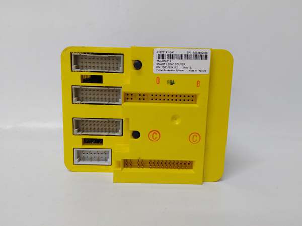
Emerson KJ2201X1-BA1
The Real-World Problem It Solves
Emergency shutdown systems in hazardous areas fail due to single-point faults when non-redundant PLCs lose a power supply or CPU card, causing the entire safety system to go dark during a process upset. Operators lose sight of valve positions and trip status right when they need it most. The KJ2201X1-BA1 brings SIL 3-capable redundant logic solving to DeltaV SIS architectures, where two logic solvers operate in parallel with voting logic—if one fails, the other takes over in <10 ms, maintaining safety function execution and operator visibility without interruption. Its galvanic isolation and hazardous area certifications (ATEX/IECEx) allow installation in Zone 2/Div. II areas where flammable gases or dust are present, eliminating the need for explosion-proof enclosures for the safety controller.
Where you’ll typically find it:
- Oil and gas production platforms (offshore/onshore) where emergency shutdown systems (ESD) must operate in Zone 1/2 hazardous environments with SIL 3 integrity
- Chemical plants and refineries with safety instrumented functions (SIFs) for emergency relief valves, shutdown valves, and fire/gas detection
- Pharmaceutical facilities with isolator valve interlocks where safety system redundancy is mandatory for GMP compliance
- Power generation facilities with turbine overspeed protection and boiler trip logic requiring deterministic <1 ms response times
Bottom line: This is a redundant SIS logic solver for DeltaV—execute safety-critical logic in <0.5 ms, survive single-point faults via redundancy, and operate in hazardous areas without additional protection.
Hardware Architecture & Under-the-Hood Logic
The KJ2201X1-BA1 is a 3U rack-mount redundant logic solver that operates in pairs (redundant configuration) within the DeltaV SIS architecture, communicating via SISnet for synchronization and voting. Each module contains its own microprocessor (Intel Celeron M410), memory, and I/O circuitry, with galvanic isolation (>2500 V RMS) between the internal logic circuits and field I/O. When installed in redundant pairs, the two solvers exchange heartbeats via SISnet at 100 Mbps and vote on logic execution—if one fails or deviates, the other takes over without process interruption. The module supports hot-swapping, allowing replacement while the redundant partner maintains safety function execution.
-
Power Supply Stage: 24 VDC input enters via a filtered terminal block with reverse polarity protection. An internal DC-DC converter generates isolated 5 VDC and 3.3 VDC rails for the microprocessor and memory. A field power output (24 VDC, 4 A max) is derived from the input bus to power field sensors/solenoids, eliminating separate field power supplies. Power supervision circuits monitor for overvoltage (>28 VDC), undervoltage (<20 VDC), and brownout conditions, triggering diagnostic LEDs if out of spec.
-
Microprocessor and Memory: The Intel Celeron M410 1.2 GHz CPU executes compiled logic code (Ladder, FBD, or Structured Text) from 256 MB DDR2 SDRAM with deterministic cycle times <0.5 ms. Configuration and logic are stored in 512 MB flash non-volatile memory, retained across power cycles. The microprocessor continuously self-tests RAM, flash, and CPU registers, logging faults to internal diagnostic buffer for retrieval via DeltaV Explorer.
-
Digital Input Stage: 16 digital input channels use opto-isolators (>1500 V RMS isolation) to sense 24 VDC field signals from switches, sensors, or limit contacts. Each input has programmable debounce filtering (1-100 ms) to reject contact chatter. Input circuits are individually configurable for wetting voltage (24 VDC from module) or dry contact sensing. Input status is read at 1 ms scan rate and stored in the microprocessor’s process image table for logic execution.
-
Digital Output Stage: 16 relay outputs use dry contact SPDT relays (2A at 24 VDC/250 VAC) driven by the microprocessor’s logic output. Each relay has separate NO and NC contacts, configurable via DeltaV Explorer for fail-safe (energize-to-trip or de-energize-to-trip). The output stage includes overcurrent protection and fault detection—if a relay contact welds or short-circuits, the module detects the anomaly via continuous monitoring and reports a “stuck contact” diagnostic alarm without tripping the fault detection system.
-
Communication Interface: The module communicates via three ports: RS-232 for programming/debug (9600/19200 baud, 8N1), RS-485 for SISnet field bus (9.6/19.2/38.4 kbps auto-detectable, redundant A/B ports), and Ethernet TCP/IP (10/100 Mbps) for HMI/SCADA integration. SISnet uses proprietary error-checking and heartbeat monitoring for redundancy—if communication to the partner solver is lost for >10 ms, the active solver enters fault mode and triggers alarms. Modbus RTU over RS-485 allows read access to I/O status and diagnostics from third-party systems.
-
Redundancy Logic: In redundant pairs, the two KJ2201X1-BA1 modules synchronize via SISnet and execute logic in lockstep. A voting algorithm compares logic outputs—if they match, the result is applied to field devices; if they diverge, the discrepancy is flagged and both modules enter safe state (all outputs to fail-safe position). Hot-swap circuitry allows removing one module without breaking the SISnet ring—the partner module maintains ring continuity and continues executing safety functions.

Emerson KJ2201X1-BA1
Field Service Pitfalls: What Rookies Get Wrong
Bypassing Field Power Removal During Replacement
Techs replace a faulty KJ2201X1-BA1 in a hazardous area without first removing field power from the terminal block, assuming the module’s internal isolation protects the wiring. The field power output (24 VDC, 4 A) remains energized during swap, and the technician shorts +24 VDC to ground while extracting the module, causing an arc flash that burns the terminal block and trips the upstream 24 VDC breaker. The entire SIS rack loses power, and safety-critical valves revert to fail-safe position—unplanned shutdown follows.
- Field Rule: Always disconnect field power at the upstream source or the terminal block before removing or inserting a KJ2201X1-BA1. Verify voltage absence with a multimeter on the field power terminals. For hazardous areas, follow permit-to-work procedures and use spark-proof tools. Never rely on the module’s internal isolation—field power is not isolated from the backplane and must be de-energized for safe swap.
Configuring Relay Fail-Safe Position Incorrectly
Engineers set all 16 relay outputs to fail-safe as “de-energized-to-trip” without checking field wiring—some safety valves are air-to-open (ATO) requiring “energized-to-trip,” while others are air-to-close (ATC) requiring “de-energized-to-trip.” During a power loss event, valves travel to the wrong position (e.g., close instead of open), causing overpressure relief failure or line overfill. Operators scramble to manually position valves while the plant alarm blares, but the safety system already failed to protect the process.
- Quick Fix: Verify fail-safe direction for each safety valve by checking the valve actuator type (spring-return ATO/ATC or double-acting). In DeltaV Explorer, configure relay outputs individually or in groups to match the field device requirement—set “energize-to-trip” for spring-return ATO valves and “de-energize-to-trip” for spring-return ATC valves. Test by cycling power on the logic solver and confirming valve movement matches safety requirements.
Mixing Non-SIS and SIS Communication on the Same Bus
Installers connect KJ2201X1-BA1 SISnet to the same RS-485 bus as standard DeltaV I/O modules, assuming the protocol is compatible. The SISnet uses proprietary error-checking and deterministic timing that conflicts with DeltaV standard I/O traffic, causing communication timeouts on both systems. The SIS solver loses synchronization with its redundant partner, and standard I/O points report “communication lost” alarms in DeltaV Explorer—neither system operates correctly, and safety functions are compromised.
- Quick Fix: Route SISnet traffic on a dedicated RS-485 bus with shielded twisted-pair cabling, physically separated from standard DeltaV I/O buses by at least 6 inches in the cabinet. Terminate the SISnet with 120Ω resistors at both ends of the bus, and use only SIS-certified switches or couplers for expansion. Never mix SISnet with Modbus or DeltaV local bus traffic—the protocols are incompatible and will cause conflicts.
Forgetting to Update Redundancy Partner After Configuration
Techs configure logic and download to the primary KJ2201X1-BA1 but fail to upload the same configuration to the redundant partner module. During normal operation, both modules execute different logic versions, causing voting divergence—the redundant pair forces a safe-state shutdown because outputs do not match. The plant loses production while engineers figure out which module has the correct configuration, and the safety system is offline for hours.
- Field Rule: Always download the exact same configuration to both redundant solvers in the pair immediately after making changes. Use DeltaV Explorer’s “Upload/Download” function for both modules, and verify the configuration checksum matches on both units (displayed in the module properties window). Test redundancy by pulling the primary module’s Ethernet cable and confirming the partner takes over without alarm divergence—this validates that both are running identical logic versions.
Ignoring SISnet Termination in Long Bus Runs
Facilities run SISnet cables over 100 meters between redundant solver pairs without adding termination resistors at both ends. The unterminated RS-485 line causes signal reflections that corrupt data packets, resulting in intermittent “communication loss” alarms on the KJ2201X1-BA1 status LEDs. Redundancy sync fails sporadically, and the safety system operates in degraded mode without voting, increasing the risk of a single-point failure causing a hazardous event.
- Quick Fix: Install 120Ω termination resistors across the A+ and B- terminals at both ends of the SISnet bus. Measure bus length—if longer than 300 meters, add additional repeaters or reduce bus speed to 9.6 kbps to improve signal integrity. Verify termination with an oscilloscope; clean waveforms show <30% overshoot on the RS-485 edges, while unterminated lines show ringing >50% with jittery packet timing.
Please note: The listed price is for reference only and is not binding. Final pricing and terms are subject to negotiation based on current market conditions and availability.


