
Description
Hard-Numbers: Technical Specifications
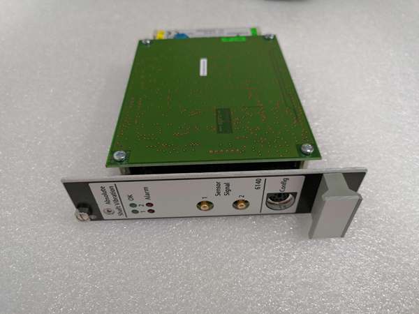
- Input Channels: 2 independent or combined monitoring modes
- Sensor Compatibility: Eddy current/displacement (Emerson PR6422/6423/6424/6425), differential Emerson sensors; input resistance >100 kΩ
- Voltage Input Range: 0 to -22 VDC (eddy current), -5 to +15 VDC (piezoelectric/seismic)
- Frequency Range: Lower cutoff 1 or 5 Hz; upper cutoff 50-2000 Hz (configurable); effective band 0.1-1000 Hz
- Dynamic Range: 0-400 mV peak-peak (low range), 0-2000 mV peak-peak (high range)
- Resolution: 0.001 mm/s RMS velocity or 0.01 μm displacement
- Communication Protocol: RS-485 Modbus RTU (supports AMS Suite Plantweb integration)
- Analog Output: 4-20 mA or 0-10 V per channel (proportional to vibration magnitude)
- Relay Outputs: 2 per channel (Alarm/Danger), configurable NO/NC with delay/hysteresis
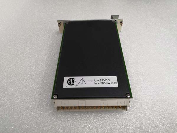
- Power Supply: 24 VDC ±10%, max 250 mA, typical consumption <6W
- Operating Temperature: 0°C to +60°C (DIN 40040 KTF class)
- Storage Temperature: -30°C to +85°C
- Humidity: Up to 95% non-condensing (EN 50081-1/EN 50082-2)
- Isolation: Galvanic isolation from power supply (>2500 VAC)
- Form Factor: 1-slot 3U size, 100×160 mm (PCB) / 3x19x12.8 cm overall
- Weight: 0.3 kg module, 0.45 kg including packaging
- Certifications: API 670 compliant, CE, NEMA 4X
EMERSON A6140-9199-00058
The Real-World Problem It Solves
Standard vibration monitoring systems using single-channel casing accelerometers miss subtle shaft motion in sleeve bearing machines where the bearing housing is heavy and doesn’t vibrate at operating speed. By the time casing vibration trips alarms, the shaft has been oscillating for days—bearing lubrication is compromised, metal-to-metal contact is occurring, and catastrophic failure is imminent. The A6140-9199-00058 brings dual-channel, direct shaft measurement to AMS 6500 systems, catching shaft displacement at 0.001 mm/s resolution—detecting bearing wear weeks before failure, not minutes. Its galvanic isolation prevents ground loops from corrupting microvolt-level signals in noisy plant environments where VFDs and large motors induce common-mode noise.
Where you’ll typically find it:
- Power plant turbine-generator sets monitoring shaft journal vibration on sleeve bearing turbines (steam, gas, hydro)
- Refinery pump rooms monitoring centrifugal compressor and boiler feed pump shafts for early bearing wear detection
- Paper mill dryer and press rolls where vibration harmonics correlate to roll eccentricity and bearing degradation
- Offshore platform crane and winch drives where shaft vibration prediction prevents unplanned production shutdowns in remote locations
Bottom line: This is a dual-channel shaft vibration monitor for AMS 6500—capture 0.001 mm/s shaft displacement before it becomes a rotor failure, isolate signals from plant ground loops, and trip machines before they wreck.
Hardware Architecture & Under-the-Hood Logic
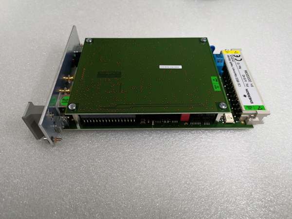
The A6140-9199-00058 is a 1-slot 3U plug-in module that sits in the AMS 6500 rack and processes dual-channel vibration data from eddy current or piezoelectric sensors. It contains its own microprocessor for real-time signal conditioning, filtering, and alarm logic, with galvanic isolation (>2500 VAC) between the input signal conditioning circuitry and the 24 VDC backplane power. The module communicates via RS-485 Modbus RTU to the AMS Suite software for configuration and real-time data streaming, and provides buffered 4-20mA/0-10V analog outputs for direct integration into DCS or PLC systems without requiring the AMS host.
-
Sensor Input Stage: Eddy current or piezoelectric sensors connect to front-panel terminals with shielded twisted-pair cabling. The input stage includes differential amplifiers with >100 kΩ input impedance, rejecting common-mode noise from long cable runs. For eddy current sensors, the module supplies -26.7 VDC excitation (max 35 mA); for piezoelectric, it supplies constant current 0-8 mA at 30 VDC. Input protection circuits clamp voltage surges above ±15 VDC to prevent ADC damage.
-
ADC and Signal Processing: A sigma-delta ADC digitizes conditioned vibration signals at configurable sampling rates (typically 10-20 kHz per channel). The module’s microprocessor applies digital bandpass filtering (lower cutoff 1/5 Hz, upper 50-2000 Hz selectable) to reject low-frequency bearing cage noise and high-frequency electrical interference. It computes RMS, peak-peak, and 1X/2X harmonic components in real time, storing peak values with timestamp for trend analysis.
-
Alarm Logic and Relay Outputs: The microprocessor compares processed vibration values against user-configured alarm and danger thresholds per channel (set via AMS 6500 software). When thresholds are exceeded, the module drives two SPDT relays per channel (Alarm and Danger) with programmable time delays (0-60 seconds) and hysteresis (0-20%) to prevent chatter. Relay contacts are dry, rated 24 VDC/250 VAC, 5A, and connect to plant safety systems or annunciation panels.
-
Analog Output Buffering: Each channel provides a proportional 4-20mA (or 0-10V) output scaled to the vibration magnitude (e.g., 4mA = 0 mm/s, 20mA = 10 mm/s full scale). The output is optically isolated from the input circuitry and buffered to drive up to 500Ω load, allowing direct connection to PLC AI cards or DCS analog input modules without additional signal conditioning.
-
Communication Interface: The module communicates via RS-485 (2-wire, half-duplex) with the AMS 6500 host or PLC/DCS systems. It operates at 9.6/19.2/38.4 kbps baud rate (auto-detectable) with 8N1 or 8E1 parity. The Modbus RTU protocol supports read/write access to configuration registers, alarm status, and live vibration values. AMS 6500 software provides real-time trend displays, alarm logging, and remote threshold adjustment via this interface.

EMERSON A6140-9199-00058
Field Service Pitfalls: What Rookies Get Wrong
Improper Sensor Gap Calibration on Eddy Current Probes
Techs install PR6422 eddy current probes without setting the mechanical gap correctly, assuming the module will “auto-calibrate.” The probe requires a 1-1.5 mm air gap from the shaft surface; incorrect gap shifts the operating voltage outside the -10 to -18 VDC linear range, causing the module to report “sensor fault” or clamp at full-scale output. The machine runs unprotected while the red FAULT LED stays on, and the vibration alarm never triggers during actual shaft movement.
- Field Rule: Always verify gap voltage at startup using a digital multimeter on the sensor input terminals. Adjust the mechanical probe position until voltage reads between -10 and -18 VDC with the shaft at rest. Lock the probe set screw and verify voltage doesn’t drift beyond ±0.5 VDC during warm-up cycle. For new installations, set gap at 1.25 mm (nominal) to account for thermal expansion.
Mixing Shield Grounding and Signal Ground at the Module
Engineers ground the sensor cable shield at both the sensor end and the module end, creating a ground loop that corrupts microvolt-level vibration signals in plants with high electromagnetic interference (e.g., near VFD cabinets or generator exciters). The A6140’s input stage picks up common-mode noise, causing vibration readings to jitter by ±0.5 mm/s RMS even with the machine idle. The alarm threshold is set too tight to avoid false trips, then the machine actually trips later from undetected vibration spikes.
- Quick Fix: Ground sensor cable shields at the sensor end only (Emerson eddy current sensors have shield terminals in the probe housing). Leave the shield floating at the A6140 input terminals—connect the signal (+/-) and ground terminals, but do not connect the shield to the module’s ground stud. For runs longer than 100 meters, install a shield isolation transformer or use differential sensor inputs (PR6424/6425) which reject common-mode noise without shielding.
Setting Alarm Thresholds Without Machine Baseline Data
New techs configure alarm and danger thresholds based on generic API 670 values (e.g., 2.0 mm/s RMS alarm, 4.0 mm/s danger) without capturing baseline vibration trends during normal machine operation. When the machine runs at 1.2 mm/s during normal load transients, the alarm trips immediately, forcing an unnecessary shutdown. Operators then disable alarms to keep the plant running, and the module sits idle during actual bearing failure events.
- Field Rule: Capture 7-14 days of baseline vibration data with AMS 6500 software before setting thresholds. Use the software’s statistical tools (mean, 2-sigma) to set alarm thresholds at 1.5x normal operating RMS and danger at 2.5x normal RMS. For sleeve bearing machines, always include phase angle analysis in alarm logic—a 30° phase shift at 1X RPM indicates developing bearing wear even if RMS stays constant.
Forggetting Modbus Termination on Long RS-485 Runs
Installers run RS-485 daisy-chain cables to the A6140 from a PLC room 500 meters away without adding termination resistors at the last module. The 24 VDC signal reflects off the unterminated line, causing intermittent communication timeouts (“Comm Error” on module status LED). AMS 6500 software loses connection to the module, and vibration data 终止s trending, leaving the machine unprotected until a tech manually resets the module.
- Quick Fix: Install a 120Ω termination resistor across the A+ and B- terminals at the last module in the RS-485 chain. For runs longer than 300 meters, also add a 120Ω resistor at the PLC/DCS end to damp reflections. Verify termination with an oscilloscope—clean Modbus waveforms show <30% overshoot; unterminated lines show ringing >50% amplitude with edge spikes.
Please note: The listed price is for reference only and is not binding. Final pricing and terms are subject to negotiation based on current market conditions and availability.


