
Description
Hard-Numbers: Technical Specifications
- Power Supply:
- Rated Connection Voltage: 3-phase 380-480 VAC (-10% to +10%)
- Mains Frequency: 48-62 Hz
- Control Voltage/Power: DC 24 V (-15% to +25%) / 1 A
- Electronics Supply: ~12 W
- Motor Output:
- Rated Current: 1.5 A (continuous)
- Rated Power: 1.1 kVA
- Peak Current: 3.75 A (1-second overload)
- Switching Frequency: 8 kHz (pulse-width modulation)
- Output Voltage: 0-480 VAC (variable frequency)
- DC Bus / Regeneration:
- DC Link Voltage: DC 530-680 V (nominal)
- Bleeder ON Power: 50 W (continuous)
- Bleeder OFF Power: 15 W/A
- Bleeder Resistance: 120 Ω
- Bleeder Capacitance: 165 µF
- Communication:
- SERCOS Interface: Fiber optic (4 MBaud data rate, EMI immune)
- Protocol: SERCOS (real-time digital bus to PacDrive Controller)
- Topology: Ring or star via fiber to PacDrive Controller MAx-4 or PacPC
- Environmental:
- Operating Temperature: +5°C to +45°C (derated above +55°C)
- Storage/Transport Temperature: -25°C to +70°C
- Humidity: 5% to 85% (non-condensing)
- Enclosure Rating: IP20 (rear terminals)
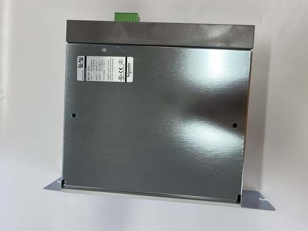
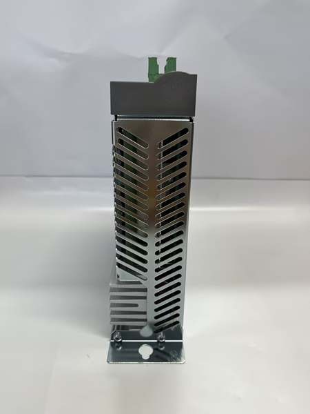
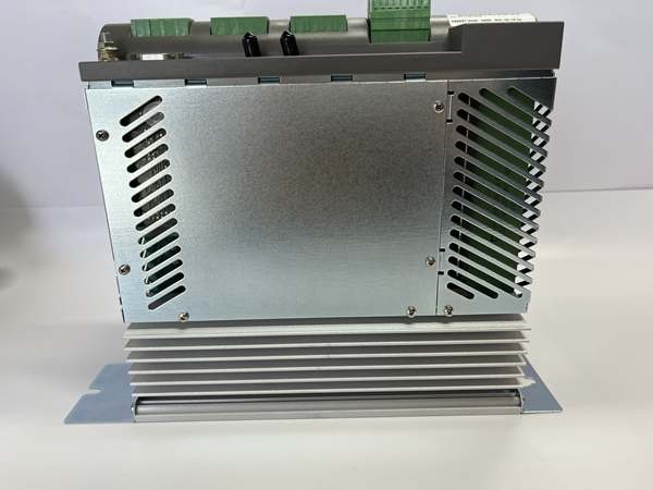
- Physical:
- Dimensions: 100 mm (W) × 400 mm (H) × 320 mm (D)
- Weight: 3.1 kg (boxed)
- Mounting: Wall-mount or cabinet mount
- Approvals:
- CE, UL, cUL
- Overvoltage Category: III, T2 (DIN VDE 0110)
- Pollution Degree: 2
- EMC Class: Class A (EN 55011 / EN 61800-3)
ELAU MC-4/11/01/400
The Real-World Problem It Solves
Running shielded power and encoder cables back to a central cabinet costs money and creates failure points when cables get cut or connectors corrode. The MC-4/11/01/400 puts the servo amplifier, mains supply, and control electronics in one compact box you can mount right next to the motor. One fiber optic cable to the controller handles all motion commands and feedback—no copper noise, no ground loops, and half the copper. When you’re dealing with 20+ axes on a blister packer or cartoner, this distributed architecture means cleaner cabinets, faster commissioning, and less troubleshooting time chasing bad terminations.
Where you’ll typically find it:
- Pharmaceutical blister packaging lines with SM-series synchronous motors requiring precise registration
- Food packaging pouch fillers where washdown environments demand distributed drives
- Labeling and print registration stations with high-speed rotary tables
- Material handling conveyors where decentralized control reduces wiring to moving carriages
Bottom line: This is a workhorse servo drive for packaging automation—mount it near the motor, run one fiber to the controller, and forget about VFD ripple or encoder cable failures.
Hardware Architecture & Under-the-Hood Logic
The MC-4/11/01/400 is a self-contained servo amplifier designed for decentralized control. It sits between the mains power and the servo motor, with a fiber optic link upstream to the PacDrive Controller. No programming lives in this unit—it’s a dumb node that receives torque, velocity, or position commands via SERCOS and closes the current loop locally.
-
Mains Input Stage: 3-phase AC (380-480V) enters through the X2 terminal block. An integrated line reactor and EMC filter smooth incoming harmonics and limit conducted emissions. The rectifier stage converts AC to DC bus voltage (nominal 530-680VDC). No external line reactor is required for most applications—ELAU built it in.
-
DC Link / Bleeder: The intermediate DC bus stores energy for the IGBT inverter stage. A regenerative bleeder circuit dumps excess energy during deceleration into a 120Ω resistor (50W dissipation). If regeneration exceeds bleeder capacity, the DC link voltage rises toward 800V and triggers an overvoltage fault. The bleeder is configurable via SERCOS parameters.
-
Inverter Stage: IGBT output stage generates variable-frequency, variable-voltage 3-phase power to the motor at 8 kHz switching frequency. The controller supports 250% overload for 1 second—critical during motor start or temporary load spikes. Current sensors (shunts or Hall effect) feed back actual motor current for closed-loop torque regulation.
-
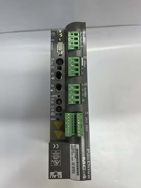
SERCOS Communication Interface: Fiber optic transceiver connects to the PacDrive Controller (MAx-4, C200, C400, P600) or PacPC. The SERCOS bus runs at 4 MBaud with deterministic timing. All setpoints (torque, velocity, position) and feedback (encoder data, status) flow over this ring. The fiber link provides complete galvanic isolation—ground potential at the drive can float relative to the controller.
-
Motor Connection (X4 Terminal) : Motor phases (U, V, W) and ground connect via screw terminals. The MC-4/11/01/400 is rated for motors up to 1.5 A continuous current. Use 16 mm² copper wire for mains, appropriate gauge for motor leads based on current and run length. Brake resistor connections (if motor has holding brake) are provided on the terminal block.
-
Control Power and I/O: 24 VDC control power (from X3 terminal) powers the internal electronics. The drive includes digital inputs for Inverter Enable (safety circuit), limit switches, and reference selection. Outputs provide fault status and ready signals. All I/O is opto-isolated where appropriate to prevent ground paths.
-
Automatic Motor Recognition: When you power up the 24V control circuit, the drive reads the electronic nameplate embedded in SM/SH servo motors. The nameplate contains motor type, rated current, voltage, and encoder data. The MC-4 auto-configures current limits, thermal time constants, and feedback parameters—no manual data entry required at startup.
ELAU MC-4/11/01/400
Field Service Pitfalls: What Rookies Get Wrong
Fiber Connectors Not Seated Before Power-UpTechs terminate the fiber patch cord but leave the connector loose at the MC-4 SERCOS port. When the system boots, the drive can’t handshake with the controller, throws a communication fault, and the motor won’t enable.
- Field Rule: Push the fiber connector until it clicks—ELAU fiber connectors have a positive tactile lock. Verify the link LED on the drive illuminates after controller power-up. If no link, swap the fiber strand (TX/RX are directional on some cords) or inspect for cracked ends.
Wrong Brake Resistor WiringConnecting a motor with holding brake but wiring the brake power supply directly to 24V control instead of the dedicated brake output terminals. The brake never releases on power-up, the drive faults with “stall” after 2 seconds, and you waste time chasing a motor that won’t turn.
- Quick Fix: Use the brake terminals on X4 (labeled B1/B2). These are switched outputs from the drive—they energize the brake when the drive is enabled and release on fault or emergency 终止. Measure brake resistance across B1-B2 (typically 20-100Ω) to confirm connection.
Ignoring Bleeder Resistor Duty CycleRunning a high-inertia load with frequent deceleration cycles on a packaging line. The integrated bleeder can’t dump regeneration fast enough, DC bus voltage creeps up, and the drive trips on overvoltage. Techs increase the bleeder resistance or add external bleeder but don’t calculate duty cycle.
- Field Rule: The internal bleeder is rated for 50W continuous. If your application has repeated deceleration cycles, calculate the regenerated energy per cycle: E = 0.5 × J × ω². If peak regen power exceeds 50W for more than 10% of duty cycle, you need an external bleeder resistor. Monitor DC bus voltage via SERCOS parameters during commissioning—it should stay under 750V during worst-case decel.
Firmware Version Mismatch with SH MotorsReplacing a failed MC-4/11/01/400 with a new unit but pulling firmware from an old backup. The drive boots, auto-detects the SH motor, then throws error code 138 “invalid motor.” The motor data format changed between firmware versions.
- Quick Fix: Check firmware version in the drive parameter block. MC-4/11/01/400 requires firmware V00.22.XX or later for SH motors (specifically SH-055 series). If you’re running older firmware, update via EPAS-4 toolkit before connecting the motor. Auto-recognition only works if firmware knows the motor nameplate format.
Grounding the DC Link MidpointConnecting the DC link midpoint to chassis ground per some old-school VFD practices. This creates a ground loop through the bleeder resistor, causes erratic motor behavior, and can blow the bleeder circuit on regen.
- Field Rule: The DC link midpoint must float on MC-4 drives. Do not connect the DC- or DC+ to earth ground. The only ground reference is the PE (protective earth) terminal on the mains input. If you have noise issues, check the motor cable shield grounding—shield to drive chassis only, not to motor earth.
Control Voltage Applied During Motor WiringApplying 24V control power to the drive while the motor leads are disconnected but the mains is still connected. The drive boots, auto-detects no motor load, and may default to a safe state. Then you energize the motor, and the sudden load application trips overcurrent protection.
- Quick Fix: Sequence power correctly: mains off → motor wired → 24V control on → controller boots → enable signal. Never wire motors under power. Lock out the mains breaker before touching X4 terminals. If you must troubleshoot hot, disable the 24V control circuit first so the drive can’t enable the IGBT stage.
Please note: The listed price is for reference only and is not binding. Final pricing and terms are subject to negotiation based on current market conditions and availability.


