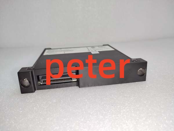
Description
Product Core Brief
- Model: 18745-03
- Brand: Bently Nevada
- Series: 3300 XL 8mm Proximity Probe System
- Core Function: Conditions the RF signal from the 8mm Proximitor probe and extension cable into a linear DC voltage representing shaft displacement.
- Product Type: 8mm Proximitor Transducer (Signal Conditioner)
- Key Specs: 8mm Probe Size | -24V DC Power | 7.87 mV/µm (200 mV/mil) Sensitivity
- Note: Requires a properly matched 8mm probe and extension cable. Verify sensitivity (mV/mil) matches your monitor module.
Key Technical Specifications
| Parameter | Specification |
|---|---|
| Product Type | 3300 XL 8mm Proximitor |
| Probe Size | 8mm (5/16 inch) |
| Power Supply | -24V DC Nominal (-22.5V to -26V DC) |
| Sensitivity | 200 mV/mil (7.87 mV/µm) Standard |
| Output Range | -2V to -18V DC (Linear) |
| Frequency Response | 0 to 10 kHz (-3 dB) |
| Operating Temp | -40°C to +177°C (-40°F to +350°F) |
| Cable Length | Must match probe + extension total length |
| Mounting | Panel Mount or DIN Rail |
| Application | Radial Vibration, Axial Displacement, Eccentricity |
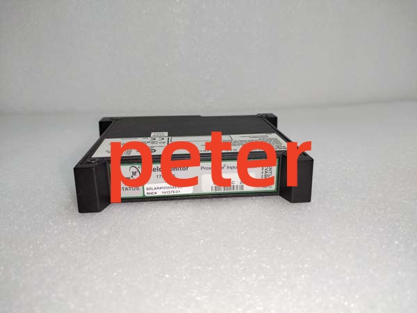
Bently Nevada 1701/15
Product Introduction
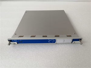
The 18745-03 is a 3300 XL 8mm Proximitor transducer designed for non-contact vibration and position monitoring of rotating machinery. It operates as part of a three-component system: probe, extension cable, and proximitors.
The 18745-03 contains the RF oscillator/detector circuitry that drives the probe tip and demodulates the reflected signal. It outputs a DC voltage inversely proportional to the gap between the probe tip and the target shaft. This voltage is then read by 3500/42M, 3300/16, or similar monitor modules to calculate vibration amplitude and static position.
QA & Testing SOP (Transparency Building)
- Incoming Inspection: Verify part number 18745-03 and date code. Inspect the BNC connector and rear terminal block for physical damage or corrosion. Check the label for correct sensitivity rating (200 mV/mil).
- Live Testing: Connect to a calibrated 8mm probe and extension cable on a test bench. Apply -24V DC power. Measure output voltage at specified gap points (e.g., -10V at nominal center gap). Verify linearity within ±2%.
- Electrical Testing: Measure input impedance and verify RF oscillator output level. Check power supply current draw (typically <15 mA). Verify output ripple is <10 mV peak-to-peak.
- Hardware Verification: Confirm all mounting nuts, washers, and locknuts are present. Inspect the rear terminal screw threads for stripping.
- Final QC & Packaging: Clean BNC connector with approved solvent. Package in anti-static shielding with desiccant. Attach QC pass tag with test date, gap-voltage calibration points, and technician ID.
Installation Pitfalls & Guide (Engineer to Engineer)
❗ Cable Length Mismatch: The 18745-03 is tuned for a specific total cable length (probe + extension). Never mix cable lengths without recalibration. A 0.5m cable error can shift the gap voltage by several volts, causing false alarms or saturation. Always verify the exact cable combination.
❗ Power Supply Polarity: The 18745-03 requires NEGATIVE power (-24V DC). Reversing polarity will destroy the internal RF oscillator. Always verify power supply wiring before connecting. Use a multimeter to confirm negative voltage at the terminal block.
❗ BNC Connector Damage: The BNC connector is the most common failure point. Never overtighten the BNC coupling nut. Hand-tight plus a quarter turn is sufficient. Stripped BNC threads require complete proximitors replacement.
❗ Ground Loop Creation: The 18745-03 chassis is typically isolated from the BNC shield. However, improper grounding at the monitor module end can create ground loops. Verify your system grounding scheme before installation to avoid 60Hz hum in vibration readings.
❗ ESD Dangers: The RF oscillator circuit is sensitive to electrostatic discharge. A static zap from an ungloved hand can degrade sensitivity or kill the unit. Always wear a grounded wrist strap when handling.
Replacement Guide:
- Pre-install: Verify probe and extension cable part numbers and total length. Confirm -24V DC power is available and correctly polarized. Ground yourself.
- Removal: Disconnect power first. Disconnect BNC from probe cable. Remove mounting nuts. Extract proximitors.
- Install: Insert new 18745-03. Secure mounting nuts (do not overtighten). Connect BNC to probe cable. Reconnect power.
- Power-on Test: Measure output voltage at nominal gap. Verify it falls within the linear range (-2V to -18V). Adjust mechanical gap if necessary to achieve target voltage (typically -9V to -11V for center range).
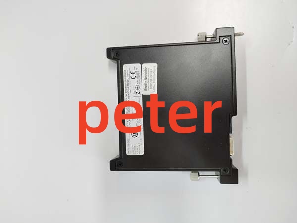
Bently Nevada 170180-01-00
FAQ (Frequently Asked Questions)
Q: Can I use this proximitors with a 5mm or 11mm probe?
A: No. The 18745-03 is specifically tuned for 8mm probes. Using it with a 5mm (18745-01) or 11mm (18745-04) probe will result in incorrect sensitivity, non-linear output, and potentially damage the probe. Always match proximitors to probe size.
Q: Why is my output voltage stuck at -2V or -18V?
A: This indicates the proximitors is saturated. Either the gap is too small (output at -2V) or too large (output at -18V). Check mechanical installation, verify cable continuity, and ensure the probe is not shorted to the target. Also verify the correct proximitors is installed for your probe size.
Q: What is the difference between 18745-03 and 330180-50-00?
A: The 18745-03 is the legacy part number for the 3300 XL 8mm Proximitor. The 330180-50-00 is the newer, functionally equivalent replacement. Both are interchangeable and share identical specifications. Bently Nevada has transitioned to the 330180-XX numbering scheme.
Q: Can I hot-swap this proximitors?
A: No. Disconnecting power while the monitor module is active can cause transient voltage spikes that may trigger false alarms. Always coordinate with operations to inhibit the channel or schedule a brief maintenance window.
Q: How do I verify the proximitors is working correctly?
A: Measure the DC output voltage with a calibrated multimeter. At nominal gap (typically 1.0mm to 1.5mm for 8mm probes), the output should be approximately -9V to -11V. Move the probe toward the target; voltage should decrease. Move away; voltage should increase. If the voltage doesn’t change or is outside -2V to -18V, the proximitors or cable is faulty.
Q: Is this part still manufactured by Bently Nevada?
A: The 3300 XL 8mm system remains an active product line. While the 18745-03 part number may be superseded by 330180-XX variants, they are fully compatible. Always verify current OEM availability and lead times. New Original and New Surplus inventory is widely available.
Q: Why does my vibration reading have excessive 60Hz noise?
A: This is typically caused by ground loops, EMI from nearby VFDs, or a damaged shield in the probe cable. Verify the proximitors chassis is properly grounded. Check that the BNC shield is intact. Route cables away from high-current conductors. Also verify the monitor module’s filter settings are appropriate for your machine speed.