

Description
Hard-Numbers: Technical Specifications
- Input Voltage Range:
- AC Input: 85-265 VAC, 47-63 Hz (single-phase)
- DC Input: 100-300 VDC
- Input Type: Universal (auto-switching between AC/DC)
- Input Current:
- At 115 VAC: 3.5 A maximum
- At 230 VAC: 1.8 A maximum
- At 220 VDC: 1.9 A maximum
- Output Voltage: 24 VDC ±5% (22.8-25.2 VDC)
- Output Channels: 4 isolated output channels (A, B, C, D)
- Output Current per Channel: 4 A maximum (each channel independently current-limited)
- Total Output Power: 96 W (24V × 4A per channel, 4 channels total)
- Output Isolation: Channel-to-channel isolation: 1000 VDC minimum; Channel-to-ground isolation: 1500 VDC minimum
- Power Factor: >0.95 at full load
- Efficiency: >85% at full load
- Ripple and Noise: <100 mV peak-to-peak (20 MHz bandwidth)
- Overcurrent Protection: Current limiting with auto-recovery at 110% of rated current
- Overvoltage Protection: Shutdown at 29-33 VDC (typical 31 VDC)
- Thermal Protection: Shutdown at 85-95°C internal temperature (auto-recovery)
- Operating Temperature: -30°C to +65°C
- Storage Temperature: -40°C to +85°C
- Humidity: 95% non-condensing
- MTBF: >200,000 hours at 40°C ambient (calculated per MIL-HDBK-217F)
- Compliance: EN 61000-6-2, EN 61010-1, IEC 61010-1, EN 60950-1, UL 60950-1, CSA C22.2 No. 60950-1, CE Mark
- Dimensions: 241.3 mm × 24.4 mm × 241.8 mm (9.50 in. × 0.96 in. × 9.52 in.)
- Weight: 1.8 kg (3.97 lb)
- Rack Space Requirements: 1 full-height front slot (power supply module) + 1 full-height rear slot (terminal block for external connections)

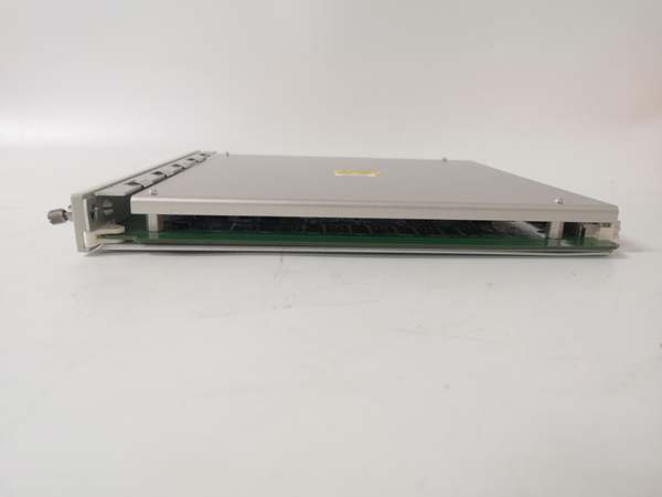
Bently 3500/60 163179-01
The Real-World Problem It Solves
You can’t afford for your entire machinery protection system to go dark because of a single power supply failure. This universal power module provides clean, isolated 24VDC power to up to four independent power domains within your 3500 rack, with redundant AC/DC inputs and N+1 redundancy support. It’s the difference between a single point of failure and a resilient power architecture that keeps your critical vibration monitoring online through power disturbances, utility glitches, or equipment room electrical faults.
Where you’ll typically find it:
- 3500 system racks in power plant turbine decks, providing redundant power with UPS backup for critical machinery protection
- Offshore oil and gas platforms, where dual power inputs (main generator + emergency diesel) ensure continuous monitoring through facility power transitions
- Refinery compressor shelters, where the power supply feeds both monitor modules and solenoid valves for emergency shutdown systems
- Hydroelectric plant control rooms, with redundant AC from grid + DC from station battery for ultimate reliability
- Pipeline pump stations, where remote installations need stable power despite grid fluctuations and lightning-induced surges
Bottom line: This is the heart of your 3500 system’s power architecture—without clean, reliable 24VDC power, all your expensive monitors, sensors, and relays are dead in the water, and you lose visibility into machinery health at the worst possible moment.
Hardware Architecture & Under-the-Hood Logic
The 177230-01-02-05 is a full-height power supply module that plugs into the 3500 rack’s front slot. It contains a universal AC/DC input stage, power factor correction, DC-DC conversion circuitry for the four isolated outputs, and comprehensive protection circuitry. The rear terminal block provides connection points for dual power inputs (AC primary + DC backup or redundant AC feeds) and status monitoring contacts.
- Universal Input Stage: Auto-switching circuitry accepts either 85-265 VAC (47-63 Hz) or 100-300 VDC. The input filter suppresses EMI and provides surge protection up to 2 kV. Power factor correction (PFC) ensures >0.95 power factor and reduces harmonic distortion.
- DC-DC Conversion: Four independent DC-DC converters generate isolated 24VDC outputs from the bulk DC bus (approximately 385 VDC after rectification and PFC). Each converter operates in continuous conduction mode for optimal efficiency and thermal performance.
- Output Isolation: Each of the four output channels (A, B, C, D) is galvanically isolated from both the input and from each other (1000 VDC minimum channel-to-channel, 1500 VDC channel-to-ground). This allows different voltage domains, ground reference schemes, or redundant power architectures within the same rack.
- Protection Circuitry:
- Overcurrent: Current limiting at 110% (4.4 A) with hiccup-mode auto-recovery
- Overvoltage: Crowbar circuit triggers at 29-33 VDC, latching off until power cycle
- Thermal: Thermal shutdown at 85-95°C PCB temperature, auto-recovery when cooled
- Input undervoltage: Hysteresis lockout prevents operation below valid input voltage
- Backplane Interface: Distributes 24VDC power to the 3500 rack backplane, which then powers all monitor modules, relay modules, and communication modules. The four output channels can be selectively assigned to different backplane power domains for redundancy.
- Status Indication: Front-panel LEDs for OK (green, normal operation), AC FAIL (yellow, AC input lost), DC FAIL (yellow, DC input lost), and PWR FAIL (red, any output fault). Also includes SPDT form C relay contacts for remote monitoring of power status (NO/NC/COM terminals on rear block)

Bently 3500/60 163179-01
Field Service Pitfalls: What Rookies Get Wrong
Misunderstanding Redundant Input WiringTechs wire both AC and DC inputs in parallel without understanding the priority logic, then wonder why the unit doesn’t automatically transfer from failed AC to DC backup.
- Field Rule: The 177230 supports OR-ing diodes for true N+1 redundancy, but the AC input has priority over DC when both are present. If you want DC priority (e.g., UPS battery takes over before AC), install an external priority relay or selector switch. The terminal block provides separate L/N/G for AC and +/− for DC—they are not internally OR’d by default.
Overloading Individual Output ChannelsAssuming all four outputs can deliver the rated 4A simultaneously, then tripping the overcurrent protection when total load exceeds 96W.
- Field Rule: Each of the four outputs can deliver 4A maximum, but the module has a total power limit of approximately 120W due to input stage and thermal constraints. Don’t expect 16A total (4A × 4 channels) continuously. Balance your load across outputs and account for peak currents during relay actuation. Monitor channel-specific current draw using the backplane monitoring software if available.
Ignoring Output Ripple in Sensitive ApplicationsUsing the power supply directly for sensitive analog sensor excitation without additional filtering, then seeing noise on vibration signals that correlates with the 24VDC switching frequency.
- Quick Fix: The 177230 has <100 mV ripple, but sensitive applications (4-20mA transmitters, high-gain vibration inputs) may need additional filtering. Use an LC filter (10μH + 100μF electrolytic) or add a dedicated low-noise linear regulator for ultra-sensitive circuits. Route 24VDC to sensor I/O modules, not directly to sensors.
Incorrect Grounding of Output ChannelsTying all four output grounds together at the terminal block, defeating the galvanic isolation and creating ground loops when different modules have different ground references.
- Field Rule: The four output channels are isolated for a reason—keep their returns separate unless your system design explicitly requires common grounding. If you need to tie channels together, do so at a single point (star ground) near the load, not at the power supply. For hazardous area applications with barrier I/O modules, keep output B isolated and reserved for intrinsically safe circuits.
Neglecting Status Relay Contact RatingWiring the status relay contacts directly to a 120VAC PLC input without checking the contact rating, then welding the contacts closed when the PLC input capacitance causes excessive inrush current.
- Field Rule: The status relay contacts are rated 30VDC / 250VAC at 0.5A maximum (resistive load). For inductive loads or higher voltages, use an external interposing relay. For 24VDC PLC inputs, you’re safe. For 120V/240VAC PLC inputs, add an interposing relay or optocoupler. The contacts are form C (SPDT)—use both NO and NC for fail-safe logic.
Forgetting to Verify Input Voltage Range Before CommissioningConnecting the unit to a 277VAC (480V wye-neutral) industrial supply in North America, exceeding the 265VAC maximum and damaging the input stage.
- Field Rule: Always verify the available voltage at the installation site before wiring. 277VAC is common in North American industrial facilities but exceeds the 177230’s 265VAC limit. You need a step-down transformer or select the DC input option (if available at 277VDC rectified, which is unlikely). In Europe/Asia, 230VAC is within spec. In 480V systems, use a 480:240V transformer or feed from a 120/208V panel.
Hot-Swapping Without Verifying RedundancyPulling a failed power supply module from a running rack without confirming that a redundant supply is online and carrying the load, causing a momentary power dip that resets monitor modules.
- Field Rule: The 3500 rack supports N+1 redundancy with dual power supplies, but only if the second supply is functioning. Before hot-swapping, verify that the backup supply’s OK LED is lit and that backplane voltage is stable. If you have only one power supply, do NOT hot-swap under load—shut down the rack first. The terminal block is designed for hot-swap, but the backplane doesn’t like zero-voltage transients.
Commercial Availability & Pricing Note
Please note: The listed price is for reference only and is not binding. Final pricing and terms are subject to negotiation based on current market conditions and availability.


