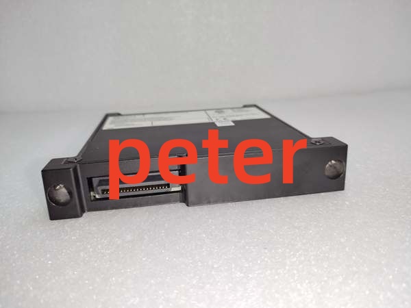
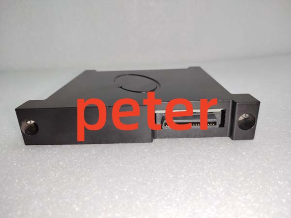
Description
Product Core Brief
- Model: 1701/15
- Brand: Bently Nevada (GE)
- Series: FieldMonitor Machinery Protection System
- Core Function: Monitors radial vibration and thrust position using Proximitor sensors for standalone machinery protection.
- Product Type: Proximitor Input Monitor
- Key Specs: Radial Vibration & Thrust Position | Direct/Gap Proportional | Alarm Time Delay
- Note: Verify Monitor Type (Radial vs. Thrust) and Transducer Scale Factor before procurement.
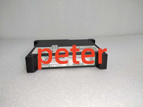
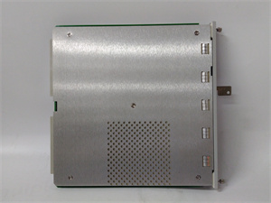
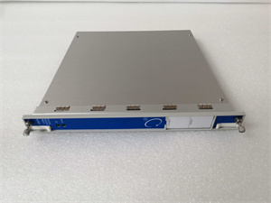
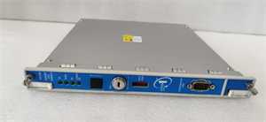
Bently Nevada 1701/15
Key Technical Specifications
| Parameter | Specification |
|---|---|
| Product Type | Proximitor Input Monitor |
| System Compatibility | Bently Nevada FieldMonitor 1701 Series |
| Supported Measurements | Radial Vibration, Thrust Position |
| Input Signal | Proximitor (Eddy Current) |
| Scaling Modes | Direct Proportional, Gap Proportional |
| Alarm Features | Alert/Danger Setpoints, Time Delay, Inhibit |
| Configuration | Transducer Type, Scale Factor, Full-Scale Range |
| Verification | Supports Internal/External Sensor Verification |
| Barrier Options | Configurable Barrier Configuration |
| Application | Rotating Machinery Protection & Monitoring |
Product Introduction
The 1701/15 is a Proximitor Input Monitor within the FieldMonitor system, designed to process signals from eddy current sensors for radial vibration and thrust position measurement. It provides critical protection functions including configurable alarm setpoints, time delays, and channel inhibit logic to prevent nuisance trips during startup or maintenance.
This module supports both direct and gap-proportional scaling, allowing flexible integration with various transducer types and scale factors. Its built-in verification capabilities and barrier configuration options ensure reliable operation in hazardous and non-hazardous industrial environments.
QA & Testing SOP (Transparency Building)
- Incoming Inspection: Verify part number 1701/15 against OEM documentation. Inspect the front-panel BNC connectors and backplane pins for physical damage or oxidation. Check the PCB for cold solder joints or thermal stress.
- Live Testing: Install in a verified FieldMonitor test frame. Inject a calibrated Proximitor signal and verify accurate radial vibration or thrust position readings in the local display or configuration software.
- Electrical Testing: Measure insulation resistance between sensor input and chassis ground (>10MΩ). Verify barrier circuit integrity if applicable. Check grounding continuity across the module chassis.
- Configuration Verification: Confirm Transducer Type, Scale Factor, and Alarm Setpoints match the application requirements. Verify Channel Inhibit and Trip Multiply settings are correctly configured.
- Final QC & Packaging: Clean BNC connectors with approved contact cleaner. Package in anti-static shielding with desiccant. Attach QC pass tag with test date, signal verification results, and technician ID.
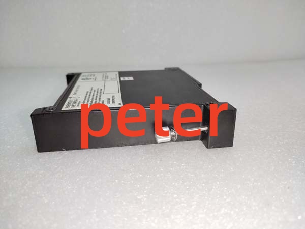
Bently Nevada 1701/15
Installation Pitfalls & Guide (Engineer to Engineer)
❗ Monitor Type Mismatch: The 1701/15 can be configured for either Radial Vibration or Thrust Position, but not both simultaneously on the same channel. Verify your application requires the correct Monitor Type before installation. Incorrect type selection will result in invalid readings or false alarms.
❗ Transducer Scale Factor Errors: The module requires the exact Transducer Scale Factor (mV/mil or mV/mm) for accurate scaling. Never guess this value. Use the sensor’s calibration sheet or perform a static calibration. Incorrect scale factors cause dangerous misreading of vibration amplitude or thrust clearance.
❗ Barrier Configuration Conflicts: If using the module in a hazardous area, verify the Barrier Configuration matches your safety barrier hardware. Mismatched barrier settings can compromise intrinsic safety or cause signal attenuation. Always cross-reference the barrier certificate with the module configuration.
❗ Alarm Time Delay Neglect: Failing to configure appropriate Alarm Time Delays can cause nuisance trips during machine startup or load changes. Always set a delay longer than the expected transient period. A 0-second delay on a large turbine startup will almost certainly cause an unnecessary shutdown.
❗ ESD Dangers: The Proximitor input circuits are extremely sensitive to electrostatic discharge. A static zap from an ungloved hand can destroy the input buffer or barrier components without visible damage. Always wear a grounded wrist strap when handling this module.
Replacement Guide:
- Pre-install: Document existing Transducer Type, Scale Factor, Alarm Setpoints, and Barrier Configuration. Disconnect all sensor cables. Ground yourself.
- Removal: De-energize the module slot. Release the locking levers and pull straight out. Do not pry. Inspect the backplane connector for debris.
- Install: Align the new 1701/15 with the backplane, slide in with even pressure, and fully engage the locking levers. Reconnect sensor cables only after mechanical seating is confirmed.
- Power-on Test: Power up the slot. Verify the module status LED. Check radial vibration or thrust position readings against a handheld meter or known-good reference. Confirm alarm logic functions correctly before returning to service.
FAQ (Frequently Asked Questions)
Q: Can I hot-swap this Proximitor Input Monitor?
A: No. The 1701/15 does not support hot-swapping. Removing it while powered will cause open-circuit conditions on the Proximitor inputs, potentially triggering false Danger alarms or damaging the input circuits. Always schedule a maintenance window and de-energize the slot.
Q: What is the difference between Radial Vibration and Thrust Position monitoring on this module?
A: Radial Vibration measures shaft displacement relative to the bearing housing in X-Y planes, while Thrust Position measures axial movement relative to a fixed reference. The 1701/15 can be configured for either, but the scaling, alarm logic, and verification procedures differ significantly. You cannot monitor both on the same channel simultaneously.
Q: Why am I getting erratic readings after replacement?
A: This is usually caused by incorrect Transducer Scale Factor, improper sensor gap, or a damaged sensor cable. Verify the scale factor matches the sensor’s calibration data. Check the sensor gap voltage (typically -9V to -11V DC for Proximitor systems). Inspect the sensor cable for damage or improper shielding.
Q: Can I use this module with non-Bently Nevada sensors?
A: Technically yes, but not recommended. The 1701/15 is calibrated for Bently Nevada Proximitor sensors. Third-party sensors may have different scale factors, frequency responses, or impedance characteristics that cause measurement errors. Always verify compatibility and recalibrate if using non-OEM sensors.
Q: What happens if I lose power suddenly?
A: The module stores its configuration in non-volatile memory. Upon power restoration, it will reload the saved Transducer Type, Scale Factor, and Alarm Setpoints automatically. If the module fails to boot or shows a fault LED, the internal flash may be corrupted, requiring a factory reset and reconfiguration.
Q: Is this part still manufactured by Bently Nevada?
A: The FieldMonitor 1701 series remains an active product line, and the 1701/15 is a standard component. However, always verify current OEM availability and lead times. For legacy installations, New Original or New Surplus inventory is typically available through authorized distributors.
Q: How do I verify the module is working correctly?
A: Use the built-in Monitor Verification function. This allows you to inject a test signal or use an internal reference to validate the measurement chain without disconnecting field sensors. Follow the verification procedure in the FieldMonitor Operation Manual (Section 8.1.4 for Radial Vibration, 8.1.6 for Thrust Position).