Description
Product Core Brief
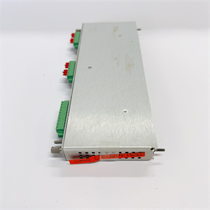
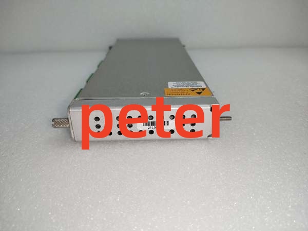
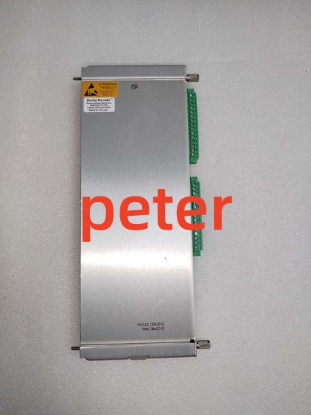
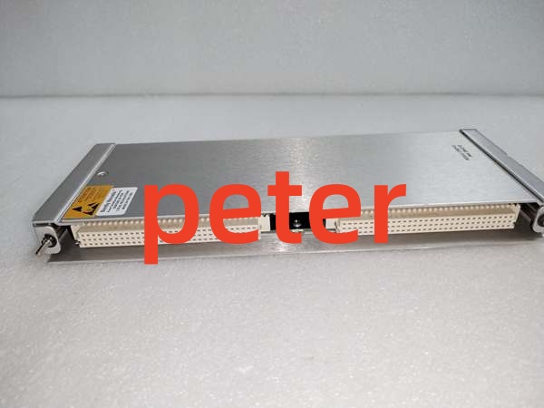
- Model: 146031-02
- Brand: Bently Nevada
- Series: 3500 Machinery Protection System
- Core Function: Serves as the Transient Data Interface (TDI) to bridge the 3500 rack with System 1 software via Ethernet, capturing both steady-state and waveform data.
- Product Type: Transient Data Interface I/O Module
- Key Specs: 100Base-FX Fiber Ethernet | 10.5W Power Draw | Slot 1 Mandatory
- Note: This module occupies Slot 1 only; verify fiber optic cabling requirements before ordering.
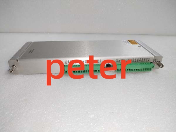
Bently Nevada 133819-01
Key Technical Specifications
- Module Type: 3500/22M Transient Data Interface (TDI)
- Network Interface: 100Base-FX Fiber Optic
- Front Panel Port: USB-B (Configuration/Service)
- Power Consumption: 10.5 Watts
- Operating Temp: -30 °C to +65 °C (-22 °F to +150 °F)
- Storage Temp: -40 °C to +85 °C (-40 °F to +185 °F)
- Humidity: 95% non-condensing
- Dimensions: 241.3 mm x 24.4 mm x 241.8 mm
- Weight: 0.82 kg (1.8 lbs)
- Slot Location: Slot 1 Only (Adjacent to Power Supply)
Product Introduction
The Bently Nevada 146031-02 is a Transient Data Interface module for the 3500/22M system, combining the functions of a Rack Interface Module (RIM) with high-speed data collection capabilities. It continuously captures steady-state and transient waveform data from M-series monitors and transmits it to System 1 software over a 100Base-FX fiber link.
This unit is critical for advanced diagnostics, enabling engineers to analyze vibration orbits, Bode plots, and waterfall data without interrupting protection logic. Its placement in Slot 1 is mandatory, and it operates independently of critical monitoring channels to ensure system stability.
QA & Testing SOP (Transparency Building)
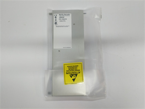
- Incoming Inspection: Verify serial number traceability; inspect fiber optic port and USB-B connector for physical damage; confirm anti-static packaging integrity.
- Live Testing: Install in Slot 1 of test rack; verify OK LED and backplane handshake; run 24-hour burn-in with active System 1 polling to check for packet loss or thermal drift.
- Electrical Testing: Measure insulation resistance (>10 MΩ at 500VDC); verify ground continuity <0.1 Ω; check 10.5W power draw stability under load.
- Firmware/Config Backup: Record exact firmware revision via 3500 Configuration Software; photograph all DIP switches and jumper settings before packing.
- Final QC & Packaging: Apply QC pass tag with test date; pack in OEM-spec anti-static bag with foam corner protectors; seal in individual box with documentation.
Installation Pitfalls & Guide (Engineer to Engineer)
❗ Slot Location Error: The TDI MUST be installed in Slot 1 (next to the power supply). Placing it in any other slot will prevent backplane communication and may cause rack initialization failures. Always verify slot numbering before insertion.
❗ Fiber vs. Copper Confusion: The 146031-02 uses 100Base-FX Fiber, not copper Ethernet. Connecting a standard RJ45 cable will not work and can damage the optical transceiver. Verify you have the correct SFP modules and fiber patch cables before powering up.
❗ Firmware Rev Mismatch: Mixing TDI revisions with older 3500/20 RIMs or other TDI modules can cause System 1 synchronization errors. Always match the exact revision or update the entire rack via 3500 Configuration Software before commissioning.
❗ Power Budget Miscalculation: This module draws 10.5W, which is higher than standard I/O cards. Calculate total backplane load including all monitors; exceeding power supply capacity causes intermittent TDI dropouts during high-data-rate events.
❗ ESD Dangers: The fiber optic transceiver and USB-B port are extremely ESD-sensitive. A single static discharge can destroy the $3,000+ communication interface. Always wear a grounded wrist strap connected to the rack chassis, not just the bench mat.
Replacement Procedure:
- Pre-install: Back up 3500 configuration and System 1 database; photograph jumpers; verify new unit revision matches.
- Removal: Power down frame (TDI is NOT hot-swappable); wait 60s for capacitor discharge; disconnect fiber and USB cables; remove module from Slot 1.
- Install: Set jumpers per photo; seat module firmly in Slot 1; reconnect fiber and USB cables; torque terminal screws to 0.5 Nm.
- Power-on Test: Apply power; verify OK LED; check 3500 Configuration Software for no faults; verify System 1 connection and data streaming.
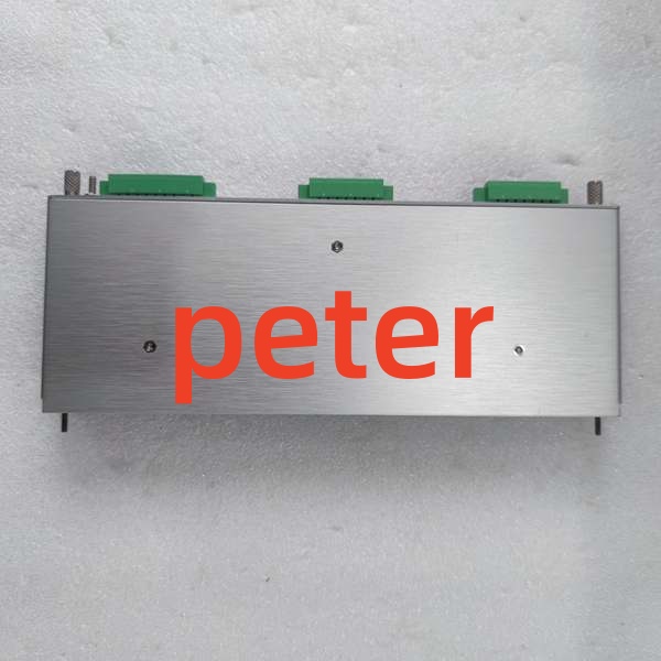
Bently Nevada 135137-01
FAQ (Frequently Asked Questions)
Q: Can I hot-swap the Bently Nevada 146031-02?
A: No. The 3500/22M TDI lacks hot-swap circuitry. Removing it under power will cause a backplane voltage disturbance, potentially corrupting the configuration of adjacent monitoring modules and risking arc damage to the backplane connector. Always perform a controlled frame shutdown.
Q: Why is my new module showing a “Comm Fail” in System 1?
A: Check the fiber optic link first. Verify the SFP modules are compatible (100Base-FX, correct wavelength) and that the fiber patch cable is not bent beyond minimum radius. Also verify the IP address configuration matches the System 1 network settings; a subnet mismatch will prevent connection.
Q: Is this module interchangeable with the 146031-01?
A: Yes, but verify the network interface. The 146031-01 typically uses 10Base-T/100Base-TX copper Ethernet, while the 146031-02 uses 100Base-FX fiber. They are functionally similar but physically incompatible. Check your existing cabling infrastructure before ordering.
Q: What happens if I lose power to this module during operation?
A: You lose System 1 data streaming and transient capture, but machinery protection remains fully operational. The TDI is not part of the critical protection path; alarms and trips continue to function via the 3500/33 relay module. Always ensure redundant power supply configuration per API 670 for data availability.
Q: How do I verify if this is a genuine Bently Nevada 146031-02?
A: Check for the Bently Nevada logo etched (not printed) on the PCB; verify the serial number matches the label; inspect the fiber optic port for factory-installed dust caps (missing caps indicate refurbishment). Request the OEM certificate of conformity from the supplier; reputable vendors provide traceability to the original Bently Nevada shipment.
Q: Can I use this module for standard Modbus communication?
A: No. The 146031-02 is designed exclusively for System 1 and 3500 Configuration Software communication. For Modbus TCP/RTU, use the 3500/92 Communication Gateway. Using the TDI for non-Bently protocols will not work and may void warranty.
Q: What’s the warranty on replacement units?
A: Standard warranty is 12 months from shipment date, covering manufacturing defects and DOA conditions. Warranty does not cover ESD damage, fiber optic port damage from improper cleaning, or physical damage from improper installation. Always retain the QC test report and original packaging for warranty claims.