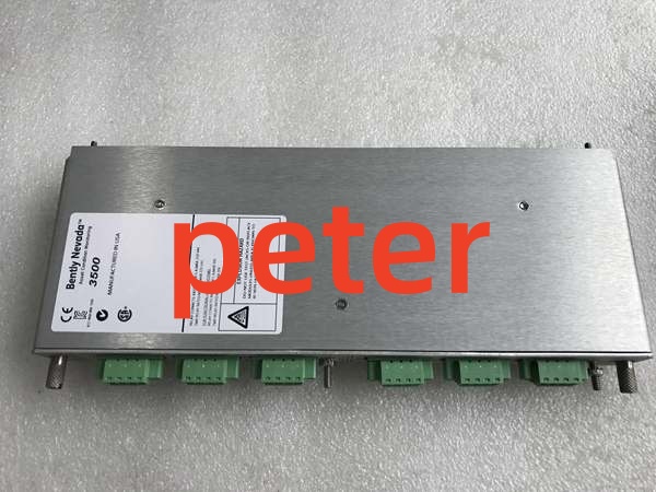
Description
Product Core Brief
- Model: 146031-01
- Brand: Bently Nevada
- Series: 3500 Machinery Protection System
- Core Function: Acts as the Transient Data Interface (TDI) linking the 3500 rack to System 1 software via 10/100Base-T Ethernet.
- Product Type: Transient Data Interface I/O Module
- Key Specs: 10Base-T/100Base-TX Ethernet | Slot 1 Placement | Static Data Capture
- Note: Requires a Channel Enable Disk to capture high-resolution dynamic waveform data.
Key Technical Specifications
| Parameter | Specification |
|---|---|
| Product Type | Transient Data Interface (TDI) I/O Module |
| System Compatibility | Bently Nevada 3500/22M Series |
| Communication Protocol | 10Base-T / 100Base-TX Ethernet |
| Required Slot Location | Slot 1 (Adjacent to Power Supply) |
| Default Data Capture | Static Data (Dynamic requires Channel Enable Disk) |
| Operating Temperature | -30°C to +65°C |
| Storage Temperature | -40°C to +85°C |
| Humidity Tolerance | Up to 95% (Non-condensing) |
| Software Integration | System 1 State Monitoring & Diagnostic Software |
| Module Height | Full-Height |
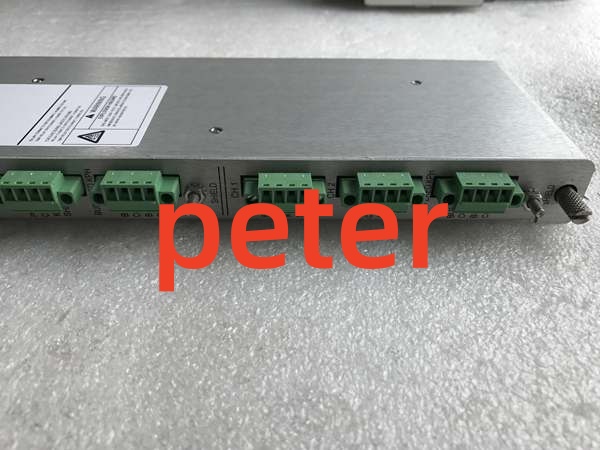
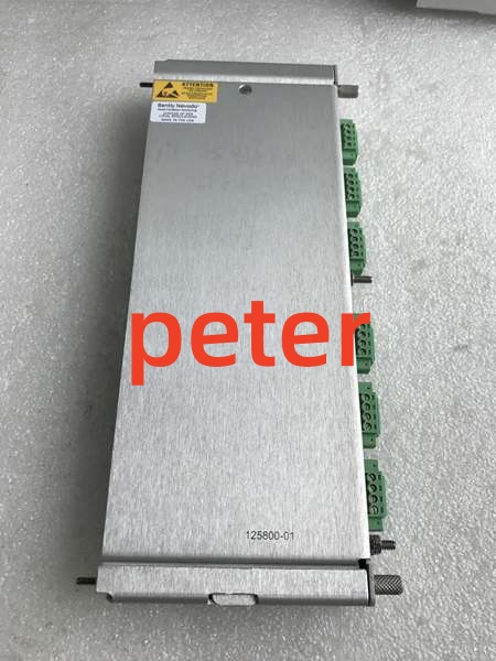
Bently Nevada 125800-01
Product Introduction
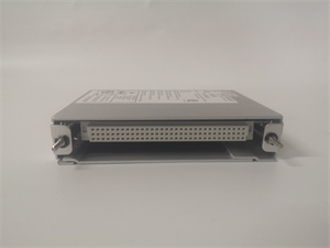
The 146031-01 is a Transient Data Interface (TDI) module that bridges the 3500 monitoring rack and the System 1 mechanical management software. It combines the functions of a Rack Interface Module (RIM) with the data collection capabilities of a communication processor.
This module continuously captures steady-state and transient waveform data, transmitting it over an Ethernet link to host software for advanced diagnostics. While it captures static data natively, adding an optional Channel Enable Disk unlocks high-resolution dynamic transient recording.
QA & Testing SOP (Transparency Building)
- Incoming Inspection: Verify part number 146031-01 against OEM documentation. Inspect the RJ45 Ethernet port for damaged locking tabs or bent pins. Check the PCB for cold solder joints or thermal stress.
- Live Testing: Install in a verified 3500 test rack in Slot 1. Verify the module establishes a link and successfully handshakes with System 1 software or 3500 Configuration Software.
- Electrical Testing: Measure insulation resistance between the Ethernet data lines and chassis ground (>10MΩ). Verify internal DC rail voltages with a calibrated Fluke 115 multimeter under load.
- Hardware Verification: Confirm the presence of the Channel Enable Disk (if dynamic data capture is required for your application). Inspect the backplane connector pins for straightness.
- Final QC & Packaging: Clean the RJ45 port and backplane contacts with approved solvent. Package in anti-static shielding with desiccant. Attach a QC pass tag with test date, link verification results, and technician ID.
Installation Pitfalls & Guide (Engineer to Engineer)
❗ Incorrect Slot Placement: The 146031-01 must be installed in Slot 1, directly adjacent to the power supply. Never install it in a standard monitor slot. Doing so will prevent backplane communication and module initialization.
❗ Missing Channel Enable Disk: This module defaults to capturing static data only. If you require high-resolution transient waveforms for fault diagnosis, you must install the optional Channel Enable Disk. Without it, dynamic data requests from System 1 will fail.
❗ Ethernet Cable Issues: The 10/100Base-TX link is sensitive to EMI in industrial environments. Always use shielded Cat5e/Cat6 cable and ensure proper grounding. Unshielded cables routed near VFDs will cause intermittent data drops and communication timeouts.
❗ Backplane Seating Issues: The 3500 backplane connector is dense and fragile. Never force insertion. If you feel resistance, pull it out and inspect both the module connector and backplane socket for bent pins. A single bent pin can corrupt the entire transient data bus.
❗ ESD Dangers: The Ethernet magnetics and data processing ICs are highly sensitive to electrostatic discharge. A static zap from an ungloved hand can fry the network port while leaving the module looking physically fine. Always wear a grounded wrist strap when handling this module.
Replacement Guide:
- Pre-install: Document IP settings and System 1 network configuration. Disconnect the Ethernet cable. Ground yourself.
- Removal: De-energize the rack slot (or perform full rack shutdown if single TDI). Release the module locking levers and pull straight out. Do not pry.
- Install: Align the new 146031-01 with the backplane in Slot 1, slide in with even pressure, and fully engage the locking levers. Reconnect the Ethernet cable only after mechanical seating is confirmed.
- Power-on Test: Power up the slot. Verify the Ethernet link LED illuminates. Ping the module and confirm data flow in System 1 software before returning to service.
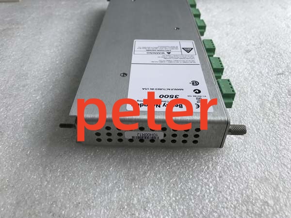
Bently Nevada 125800-01
FAQ (Frequently Asked Questions)
Q: Can I hot-swap this Transient Data Interface module?
A: No. The 146031-01 does not support hot-swapping. Removing it while powered will disrupt the communication bus and halt all data flow to System 1 software. Always schedule a maintenance window and de-energize the slot.
Q: What is the difference between 146031-01 and 146031-02?
A: The suffix dictates the physical network interface. The 146031-01 uses standard 10Base-T/100Base-TX copper Ethernet (RJ45). The 146031-02 uses 100Base-FX fiber optic Ethernet. Verify your network infrastructure before ordering.
Q: Why is System 1 not receiving transient waveform data?
A: This is typically caused by a missing Channel Enable Disk. The 146031-01 only captures static data natively. Verify that the Channel Enable Disk is properly installed and configured in the 3500 software. Also check the Ethernet link status and IP configuration.
Q: Does this module affect critical machinery protection?
A: No. The TDI is not part of the critical monitoring channel. If this module fails, the 3500 monitors will continue to protect the machinery and drive local relays. However, you will lose historical data trending and remote diagnostics via System 1.
Q: Can I use this module in a Triple Modular Redundancy (TMR) rack?
A: Standard 146031-01 modules are not designed for TMR applications. TMR configurations require a specific TMR-rated TDI module that performs real-time monitor channel comparison and voting. Verify your safety architecture requirements before procurement.
Q: What happens if I lose power suddenly?
A: The module stores its configuration in non-volatile memory. Upon power restoration, it will automatically reconnect to System 1 and resume data collection. If the module fails to boot or shows a fault LED, the internal flash may be corrupted, requiring a factory reset and reconfiguration.
Q: Is this part still manufactured by Bently Nevada?
A: The 3500 system remains an active product line, and the 146031-01 is a standard component. However, always verify current OEM availability and lead times. For legacy installations, New Original or New Surplus inventory is typically available through authorized distributors.