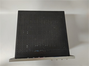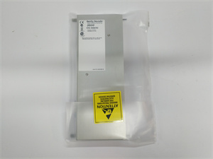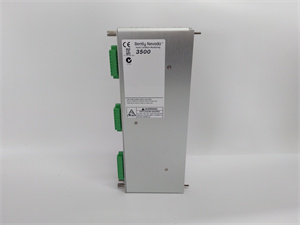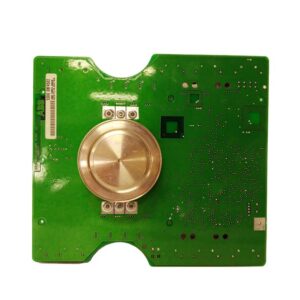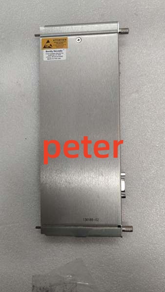
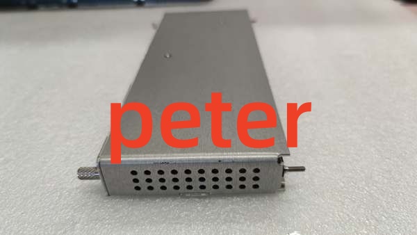
Description
Product Core Brief
- Model: 136188-01
- Brand: Bently Nevada
- Series: 3500/92 Relay I/O Module
- Core Function: Provides four independently programmable relay outputs for executing alarm and shutdown logic.
- Product Type: 4-Channel Relay Output Module
- Key Specs: 4 Independent Channels | AND/OR Logic | 3500 Rack Compatible
- Note: For Triple Modular Redundancy (TMR) applications, use the 3500/34 TMR Relay Module instead.
Key Technical Specifications
| Parameter | Specification |
|---|---|
| Product Type | 4-Channel Relay Output Module |
| System Compatibility | Bently Nevada 3500 Series Rack |
| Channel Count | 4 Independent Relay Outputs |
| Module Height | Full-Height |
| Logic Programming | AND / OR Gate Logic |
| Slot Placement | Right of Frame Interface Module (RIM) |
| Status Indicators | OK LED, TX/RX LED, CH ALARM LED |
| Configuration | 3500 Frame Configuration Software |
| Application | Machinery Protection, Alarm/Shutdown Output |
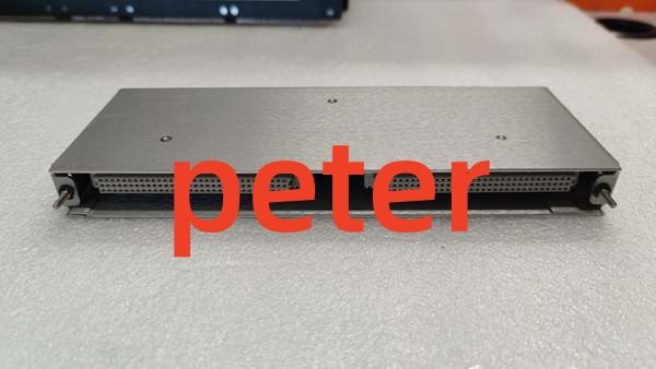
Bently Nevada 136188-01
Product Introduction
The 136188-01 is a full-height 4-channel relay module for the Bently Nevada 3500 Machinery Protection System. It provides discrete relay outputs to drive external plant alarms, shutdown sequences, and control logic based on monitored machinery parameters.
Each of the four relay outputs can be independently programmed using the 3500 Frame Configuration Software. The module supports flexible AND/OR gate logic, allowing engineers to combine alarm inputs from any monitor channel in the rack to trigger specific relay actions based on application requirements.
QA & Testing SOP (Transparency Building)
- Incoming Inspection: Verify part number 136188-01 against OEM documentation. Inspect the backplane connector pins for straightness and oxidation. Check relay housings for physical damage or corrosion.
- Live Testing: Install in a verified 3500 test rack. Force each of the four relay channels via configuration software and verify audible click and physical actuation. Confirm OK and TX/RX LEDs illuminate correctly.
- Electrical Testing: Measure contact resistance across each relay under load. Verify insulation resistance between relay contacts and chassis ground (>10MΩ). Check grounding continuity.
- Hardware Verification: Confirm all mounting hardware and connector locks are present and functional. Inspect the front panel labeling for legibility.
- Final QC & Packaging: Clean contact surfaces and backplane connector with approved solvent. Package in anti-static shielding with desiccant. Attach QC pass tag with test date, channel verification results, and technician ID.
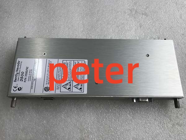
Bently Nevada 136188-01
Installation Pitfalls & Guide (Engineer to Engineer)
❗ TMR Requirement Misunderstanding: This module is NOT suitable for Triple Modular Redundancy (TMR) applications. If your safety architecture requires TMR, you must use the 3500/34 TMR Relay Module. Using this standard relay module in a TMR system will compromise your safety integrity level.
❗ Slot Placement Errors: The 136188-01 must be installed to the right of the Frame Interface Module (RIM). Never install it in a standard monitor slot or to the left of the RIM. Incorrect slot placement will prevent backplane communication and module initialization.
❗ Logic Programming Errors: Each relay requires explicit AND/OR logic programming in the 3500 configuration software. Unconfigured relays will remain in their default state. Always verify relay logic mapping against the P&ID before commissioning. A misconfigured shutdown relay can cause unnecessary trips or fail to trip when needed.
❗ Backplane Seating Issues: The 3500 backplane connector is dense and fragile. Never force insertion. If you feel resistance, pull it out and inspect both the module connector and backplane socket for bent pins. A single bent pin can corrupt the entire relay bus.
❗ ESD Dangers: The relay driver circuitry is sensitive to electrostatic discharge. A static zap from an ungloved hand can destroy individual channel drivers without visible damage. Always wear a grounded wrist strap when handling this module.
Replacement Guide:
- Pre-install: Document existing relay configuration and wiring. Verify slot placement is correct. Disconnect all field wiring. Ground yourself.
- Removal: De-energize the rack slot. Release the module locking levers and pull straight out. Do not pry. Inspect the backplane connector for debris.
- Install: Align the new 136188-01 with the backplane, slide in with even pressure, and fully engage the locking levers. Reconnect field wiring only after mechanical seating is confirmed.
- Power-on Test: Power up the slot. Verify OK LED flashes and TX/RX LED indicates communication. Force each channel via software to confirm proper operation. Check CH ALARM LED behavior matches configuration.
FAQ (Frequently Asked Questions)
Q: Can I hot-swap this relay module?
A: No. The 136188-01 does not support hot-swapping. Removing it while powered can cause transient voltage spikes on the backplane relay bus, potentially disrupting other modules or causing false trips. Always schedule a maintenance window and de-energize the slot.
Q: What do the front panel LEDs indicate?
A: The OK LED flashes when the module is operating normally. The TX/RX LED flashes when the module is successfully communicating with other modules in the rack. The CH ALARM LED flashes when the corresponding relay channel is in an active alarm state. If the OK LED is not flashing, the module has a fault.
Q: Can I use this module for safety-rated shutdown functions?
A: Verify the module’s SIL (Safety Integrity Level) rating with the OEM documentation. While the 136188-01 is designed for machinery protection, safety-rated shutdown applications may require specific certification and configuration. For TMR safety architectures, always use the 3500/34 module instead.
Q: How many of these modules can I install in one rack?
A: You can install any number of 4-channel relay modules, as long as they are placed in available slots to the right of the Frame Interface Module. Each module adds four independent relay outputs to your system. Just ensure your power supply has adequate headroom for the additional modules.
Q: Why is my relay not energizing even though the alarm is active?
A: This is typically caused by incorrect AND/OR logic programming. Verify in the 3500 configuration software that the correct monitor channels and alarm states (Alert or Danger) are mapped to the specific relay output. Also check that the relay is not inhibited or forced in the software.
Q: What happens if one relay channel fails?
A: The four channels are independent, so a single channel failure does not affect the others. However, you should replace the module at the next maintenance opportunity. Configure your alarm logic to detect relay failures and alert operators before critical protection functions are compromised.
Q: Is this part still manufactured by Bently Nevada?
A: The 3500 system remains an active product line, and the 136188-01 is a standard component. However, always verify current OEM availability and lead times. For legacy installations, New Original or New Surplus inventory is typically available through authorized distributors.