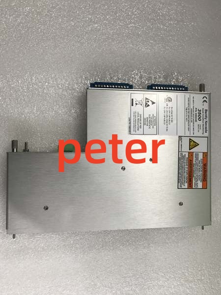
Description
Product Core Brief
- Model: 135489-04
- Brand: Bently Nevada
- Series: 3500 Machinery Protection System
- Core Function: Processes signals from eddy current probes or magnetic pickups to provide precise speed and phase reference for the 3500/25 Keyphasor monitor.
- Product Type: Tachometer / Keyphasor I/O Module
- Key Specs: Dual Channel Input | 3500/25 Compatible | 0.1 RPM Resolution
- Note: Verify sensor compatibility and threshold settings against existing configuration.
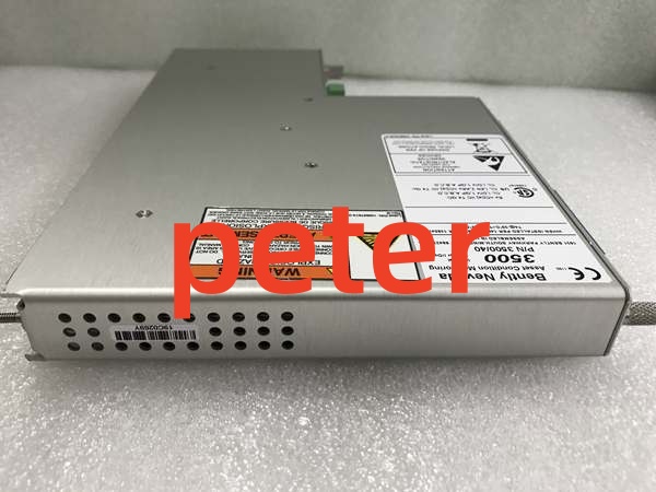
Bently Nevada 135489-04
Key Technical Specifications
- Compatible Monitor: 3500/25 Keyphasor Module
- Sensor Input: Eddy Current Proximity Probe, Magnetic Pickup
- Speed Measurement Range: 0.1 to 30,000 RPM
- Speed Resolution: 0.1 RPM
- Keyphasor Pulse Range: 1 to 10 kHz
- Input Impedance: 10 kΩ (Speed), 50 kΩ (Keyphasor)
- Operating Temp: -40 °C to +85 °C
- Power Consumption: ≤ 4 Watts
- Outputs: TTL Level Keyphasor Pulse, 4-20 mA (Speed)
- Mounting: 3500 Rack Backplane
Product Introduction
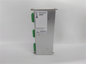
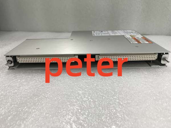
The Bently Nevada 135489-04 is a Tachometer and Keyphasor I/O module designed for the 3500/25 monitor. It receives analog signals from shaft-mounted sensors and converts them into precise digital timing references and speed measurements for the 3500 backplane.
This module enables accurate measurement of shaft speed and provides the critical phase reference needed for vibration vector analysis. Its high-resolution speed measurement and reliable keyphasor pulse generation ensure dependable machinery protection and diagnostic capabilities.
QA & Testing SOP (Transparency Building)
- Incoming Inspection: Verify serial number traceability against OEM records; inspect PCB for rework, corrosion, or damaged edge connectors; confirm anti-static packaging integrity.
- Live Testing: Install in 3500/25 test rack; verify OK LED and backplane communication; inject simulated tachometer and keyphasor signals to validate speed calculation and pulse timing.
- Electrical Testing: Measure insulation resistance (>10 MΩ at 500VDC); verify ground continuity <0.1 Ω; check input signal conditioning circuit response.
- Firmware/Config Backup: Record exact firmware revision via 3500 Configuration Software; photograph all DIP switches and jumper settings before packing.
- Final QC & Packaging: Apply QC pass tag with test date; pack in OEM-spec anti-static bag with foam corner protectors; seal in individual box with documentation.
Installation Pitfalls & Guide (Engineer to Engineer)
❗ Firmware Rev Mismatch: Mixing revisions in a 3500/25 slot can cause keyphasor signal processing errors or communication timeouts. Always match the exact revision of the replaced unit or update the entire frame via 3500 Configuration Software before commissioning.
❗ DIP Switch/Jumper Errors: Channel configuration and threshold settings are critical. Take a high-res photo of the old module’s jumper settings before removal. Incorrect threshold selection will cause missed pulses or false triggering at low shaft speeds.
❗ Wiring Incompatibilities: Input signal conditioning differs between eddy current and magnetic pickup sensors. Do not assume wire-for-wire compatibility. Verify terminal block labeling against the 3500/25 manual; incorrect wiring can damage the input stage.
❗ Power Draw Changes: This module draws ≤4W from the backplane. Calculate total backplane load including all I/O modules; exceeding power supply capacity causes intermittent resets during high-speed operation.
❗ ESD Dangers: The keyphasor input stage is extremely ESD-sensitive. A single static discharge can destroy the signal conditioning circuitry. Always wear a grounded wrist strap connected to the rack chassis, not just the bench mat.
Replacement Procedure:
- Pre-install: Back up 3500/25 configuration; photograph jumpers; verify new unit revision matches.
- Removal: Power down frame (3500/25 is NOT hot-swappable); wait 60s for capacitor discharge; remove module.
- Install: Set jumpers per photo; seat module firmly; torque terminal screws to 0.5 Nm.
- Power-on Test: Apply power; verify OK LED; check 3500 Configuration Software for no faults; rotate shaft and verify keyphasor pulse detection and speed reading.
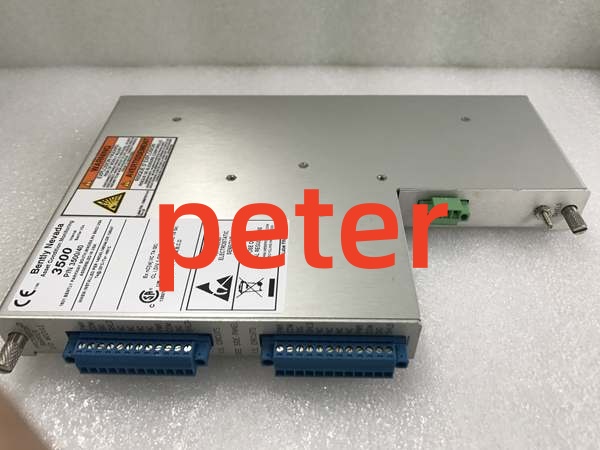
Bently Nevada 135489-04
FAQ (Frequently Asked Questions)
Q: Can I hot-swap the Bently Nevada 135489-04?
A: No. The 3500/25 Keyphasor I/O module lacks hot-swap circuitry. Removing it under power will cause a backplane voltage disturbance, potentially corrupting the configuration of adjacent monitoring modules and risking arc damage to the backplane connector. Always perform a controlled frame shutdown.
Q: Why is my new module not detecting keyphasor pulses?
A: Check the threshold setting first. Verify the sensor signal exceeds the minimum trigger amplitude. Also verify the sensor gap and that the keyway/tab is properly aligned with the probe. Incorrect sensor type configuration (eddy current vs. magnetic) will cause complete signal loss.
Q: Is this module interchangeable with other 3500 I/O modules?
A: No. The 135489-04 is specifically engineered for the 3500/25 Keyphasor monitor. It has unique signal conditioning for speed and phase measurements that differs from vibration or temperature modules. Forcing the wrong module into the slot will not work and may damage the backplane.
Q: What happens if I lose power to this module during operation?
A: You lose all keyphasor timing references and speed monitoring. Without keyphasor signals, the 3500 system cannot calculate phase angles or synchronous vibration vectors. Always ensure redundant power supply configuration per API 670.
Q: How do I verify if this is a genuine Bently Nevada 135489-04?
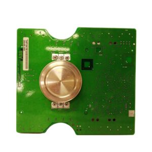
A: Check for the Bently Nevada logo etched (not printed) on the PCB; verify the serial number matches the label; inspect solder joints for machine-wave consistency (hand-soldered joints indicate refurbishment or counterfeit). Request the OEM certificate of conformity from the supplier; reputable vendors provide traceability to the original Bently Nevada shipment.
Q: Can I use magnetic pickups with this module?
A: Yes, but note the minimum speed requirement. Passive magnetic pickups require sufficient shaft speed to generate adequate signal amplitude. For low-speed or zero-speed applications, use eddy current proximity probes instead.
Q: What’s the warranty on replacement units?
A: Standard warranty is 12 months from shipment date, covering manufacturing defects and DOA conditions. Warranty does not cover ESD damage, overvoltage from incorrect wiring, or physical damage from improper installation. Always retain the QC test report and original packaging for warranty claims.