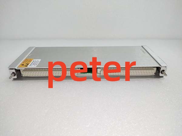
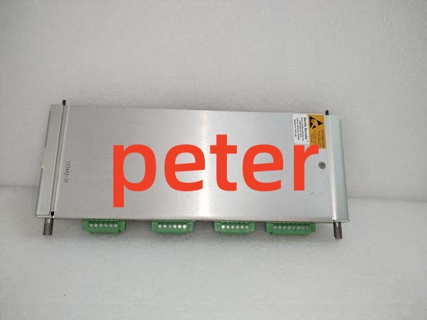
Description
Product Core Brief
- Model: 133442-01
- Brand: Bently Nevada
- Series: 3500 Machinery Protection System
- Core Function: Provides precise speed measurement and monitoring for various industrial rotating machinery applications.
- Product Type: Tachometer I/O Module (3500/50)
- Key Specs: Internal Termination | High Precision | 3500 Rack Compatible
- Note: Verify exact 3500/50 sub-model compatibility before procurement.
Key Technical Specifications
| Parameter | Specification |
|---|---|
| Product Type | Tachometer I/O Module with Internal Termination |
| System Compatibility | Bently Nevada 3500 Series |
| Core Function | Precise Speed Measurement and Monitoring |
| Termination | Internal Termination |
| Form Factor | Compact Industrial Module |
| Performance | High Precision, Reliable Data Acquisition |
| Application | Manufacturing, Energy, Transportation |
| Integration | Compatible with Various Monitoring Systems |
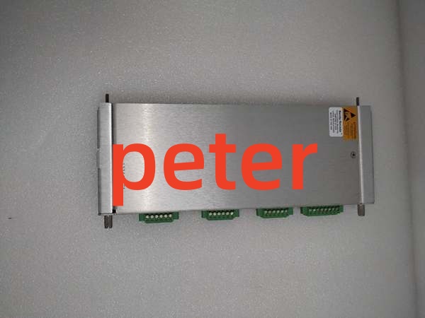
Bently Nevada 133442-01
Product Introduction
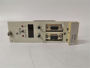
The 133442-01 is a high-performance Tachometer I/O module designed for the Bently Nevada 3500 Machinery Protection System. It is specifically engineered to measure and monitor rotational speed across a wide variety of industrial applications.
This module delivers accurate, real-time speed data with internal termination for simplified wiring. Its compact design and reliable performance make it ideal for critical monitoring in demanding environments like power generation and heavy manufacturing.
QA & Testing SOP (Transparency Building)
- Incoming Inspection: Verify part number 133442-01 against OEM documentation. Inspect the backplane connector pins for straightness and oxidation. Check the PCB for cold solder joints or physical damage.
- Live Testing: Install in a verified 3500 test rack. Inject a calibrated frequency signal and verify the module accurately reports speed values in System 1 software.
- Electrical Testing: Measure insulation resistance on input channels (>10MΩ). Verify internal termination resistor values using a calibrated Fluke 115 multimeter. Check grounding continuity.
- Hardware Verification: Confirm all mounting hardware and connector locks are present and functional. Inspect the front panel labeling for legibility.
- Final QC & Packaging: Clean contact surfaces with approved solvent. Package in anti-static shielding with desiccant. Attach QC pass tag with test date, frequency verification results, and technician ID.
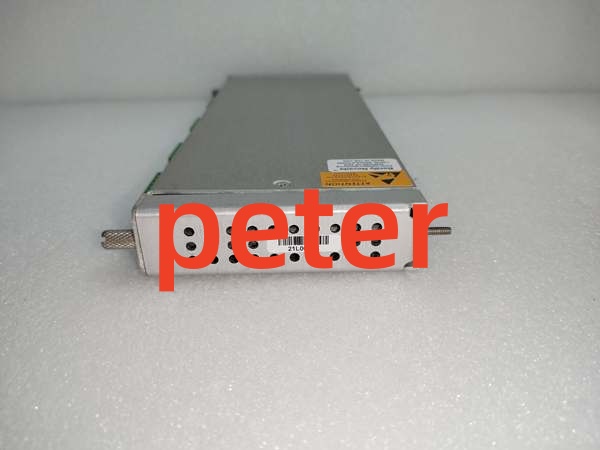
Bently Nevada 133442-01
Installation Pitfalls & Guide (Engineer to Engineer)
❗ Termination Mismatch: This module features internal termination. Never add external termination resistors at the module end. Doing so will cause signal reflection issues and erratic speed readings. Verify your field wiring matches the internal termination configuration.
❗ Signal Level Incompatibility: The 133442-01 expects specific tachometer signal amplitudes. Never connect high-voltage signals directly. If your field sensor outputs a non-standard signal, use an appropriate signal conditioner to prevent destroying the input buffer ICs.
❗ Backplane Seating Issues: The 3500 backplane connector is dense and fragile. Never force insertion. If you feel resistance, pull it out and inspect both the module connector and backplane socket for bent pins. A single bent pin can corrupt the entire speed measurement bus.
❗ ESD Dangers: The high-precision input circuitry is extremely sensitive to electrostatic discharge. A static zap from an ungloved hand can degrade measurement accuracy without visible damage. Always wear a grounded wrist strap when handling this module.
❗ Configuration Errors: The module requires proper configuration for your specific sensor type and gear tooth count. Unconfigured or misconfigured modules will display incorrect RPM. Always verify the sensor scaling parameters in System 1 before returning to service.
Replacement Guide:
- Pre-install: Document existing sensor wiring and configuration parameters. Disconnect all field cables. Ground yourself.
- Removal: De-energize the rack slot. Release the module locking levers and pull straight out. Do not pry.
- Install: Align the new 133442-01 with the backplane, slide in with even pressure, and fully engage the locking levers. Reconnect field cables only after mechanical seating is confirmed.
- Power-on Test: Power up the slot. Verify the module status LED. Inject a test frequency or verify live RPM against a handheld tachometer. Confirm no new alarms are active before returning to service.
FAQ (Frequently Asked Questions)
Q: Can I hot-swap this tachometer I/O module?
A: No. The 133442-01 does not support hot-swapping. Removing it while powered will cause open-circuit conditions on the tachometer inputs, potentially triggering false overspeed alarms or damaging the input circuits. Always schedule a maintenance window and de-energize the slot.
Q: What is the difference between 133442-01 and 286566-02?
A: The 133442-01 is the specific I/O module with internal termination, while 286566-02 typically refers to a complete 3500/50 Tachometer Monitor assembly. Verify whether you need just the I/O front card or the complete monitor module for your application.
Q: Why am I getting erratic speed readings after replacement?
A: This is usually caused by improper signal conditioning, incorrect gear tooth count configuration, or EMI interference. Verify the sensor gap voltage or signal amplitude. Check that the module is properly configured for your specific sensor type. Ensure field cables are shielded and routed away from VFDs.
Q: Can I use this module with magnetic pickup sensors?
A: Yes, the 133442-01 is designed to accept standard magnetic pickup and active tachometer signals. However, verify the signal amplitude and frequency range match the module’s specifications. Weak signals from worn magnetic pickups may require signal conditioning before reaching this module.
Q: What happens if I lose power suddenly?
A: The module stores its configuration in non-volatile memory. Upon power restoration, it will reload the saved scaling parameters and alarm setpoints automatically. If the module fails to boot or shows a fault LED, the internal flash may be corrupted, requiring a factory reset and reconfiguration.
Q: Is this part still manufactured by Bently Nevada?
A: The 3500 system remains an active product line, and the 133442-01 is a standard component. However, always verify current OEM availability and lead times. For legacy installations, New Original or New Surplus inventory is typically available through authorized distributors.
Q: Why does my speed reading show zero when the machine is running?
A: Check for open-circuit field wiring, failed sensor, or incorrect input configuration. Verify the sensor is generating a signal with an oscilloscope or frequency counter. Also confirm the module is configured for the correct input type (active vs. passive sensor). A misconfigured input threshold can reject valid signals.