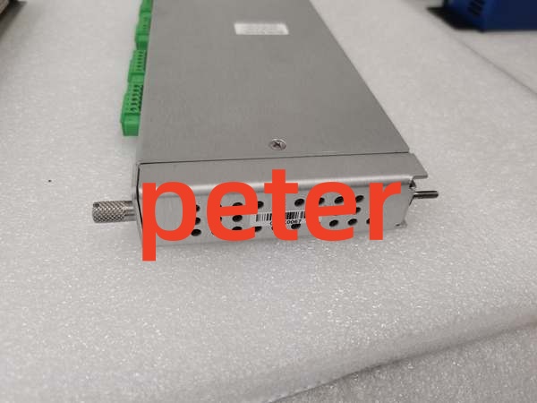
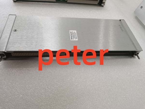
Description
Product Core Brief
- Model: 125720-01
- Brand: Bently Nevada
- Series: 3500 Machinery Protection System
- Core Function: Provides four independent relay outputs for driving external alarms, shutdowns, and control logic.
- Product Type: 4-Channel Relay I/O Module
- Key Specs: 4 Channels | Relay Output | Backup/Redundant Function
- Note: Verify compatibility with 3500/32M or similar relay driver modules.
Key Technical Specifications
- Product Type: 4-Channel Relay I/O Module
- System Compatibility: Bently Nevada 3500 Series
- Channel Count: 4 Independent Relay Outputs
- Function: Signal conversion, alarm/shutdown output, and system backup
- Module Type: Relay Output Interface
- Application: Industrial automation, rotating machinery protection
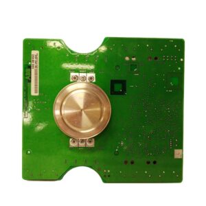
- Design: Compact, high-reliability circuit board
- Integration: Plug-and-play into 3500 rack backplane

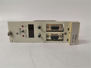
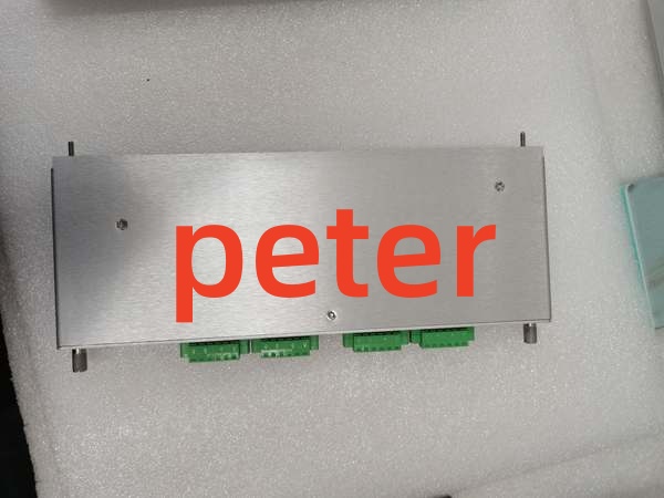
Bently Nevada 125720-01
Product Introduction
The 125720-01 is a dedicated 4-channel relay I/O module for the 3500 Machinery Protection System. It translates internal monitoring logic into discrete relay outputs to drive external alarms, ESD shutdowns, and plant control logic.
This module provides critical backup functionality to ensure system continuity during primary controller faults. Its four independent channels allow simultaneous handling of multiple alarm states, maintaining high reliability and stability in harsh industrial environments.
QA & Testing SOP (Transparency Building)
- Incoming Inspection: Verify part number 125720-01 against OEM documentation. Inspect PCB for cold solder joints, cracked traces, or damaged relay housings. Check backplane connector pins for straightness and oxidation.
- Live Testing: Install in a verified 3500 test rack. Force each of the four relay channels via configuration software and verify audible click and physical actuation. Measure contact resistance under load.
- Electrical Testing: Measure insulation resistance between relay contacts and chassis ground (>10MΩ). Verify coil drive voltage using a calibrated Fluke 115 multimeter. Check for proper grounding continuity.
- Hardware Verification: Confirm all mounting hardware and connector locks are present and functional. Inspect relay part numbers against OEM specifications for replacement verification.
- Final QC & Packaging: Clean contact surfaces and backplane connector with approved solvent. Package in anti-static shielding with desiccant. Attach QC pass tag with test date, channel verification results, and technician ID.
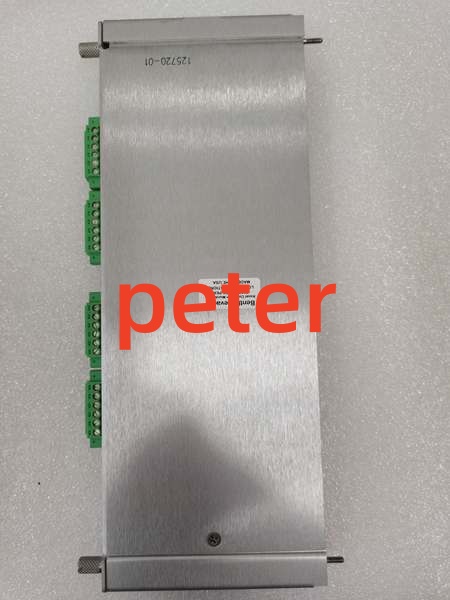
Bently Nevada 125720-01
Installation Pitfalls & Guide (Engineer to Engineer)
❗ Relay Contact Rating Exceeded: This module is for signal-level switching, not high-power loads. Never exceed the OEM-specified contact rating. I’ve seen relay contacts welded shut by operators trying to drive solenoids directly. Always use an interposing relay for high-current loads.
❗ Backplane Seating Issues: The 3500 backplane connector is dense and fragile. Never force insertion. If you feel resistance, pull it out and inspect both the module connector and backplane socket for bent pins. A single bent pin can corrupt the entire relay bus.
❗ Wiring Polarity and Grounding: Relay outputs are typically dry contacts, but verify your specific application. Incorrect wiring can backfeed voltage into the module and destroy the driver ICs. Always use shielded cable for relay wiring in high-EMI environments and ground shields at one end only.
❗ ESD Dangers: The relay driver circuitry is highly sensitive to electrostatic discharge. A static zap from an ungloved hand can kill individual channels without visible damage. Always wear a grounded wrist strap when handling this module.
❗ Configuration Mismatch: The 125720-01 requires proper configuration in the 3500 System 1 software. Unconfigured or misconfigured relays will remain in a default state (usually de-energized). Always verify relay logic and alarm setpoints before returning to service.
Replacement Guide:
- Pre-install: Document existing relay configuration and wiring. Verify power supply headroom and ground yourself.
- Removal: De-energize the rack slot. Disconnect all field wiring before unclamping the module. Pull straight out—no prying.
- Install: Align the backplane connector carefully, then slide in with even pressure. Re-engage locking levers fully. Reconnect field wiring only after mechanical seating is confirmed.
- Power-on Test: Power up the slot, verify relay status LEDs, and force each channel via software to confirm proper operation. Check System Health menu for communication errors before returning to service.
FAQ (Frequently Asked Questions)
Q: Can I hot-swap this relay module?
A: No. The 125720-01 does not support hot-swapping. Removing it while powered can cause transient voltage spikes on the backplane relay bus, potentially damaging adjacent modules or causing false trips. Always schedule a maintenance window and de-energize the slot.
Q: Why are my relays chattering or failing prematurely?
A: Relay chatter is typically caused by electrical noise on the coil drive circuit or insufficient contact protection. Verify that snubber circuits or flyback diodes are installed across inductive loads. Also check for EMI interference from nearby VFDs or large contactors. Mechanical vibration can also accelerate relay wear—ensure the module is properly seated and the rack is adequately damped.
Q: Is this module compatible with 3500/32M relay driver modules?
A: Yes, the 125720-01 is designed to work with 3500/32M and similar relay driver modules in the 3500 system. However, always verify firmware compatibility and configuration requirements. Mismatched firmware versions can cause relay timing issues or communication faults.
Q: What happens if one relay channel fails?
A: The 125720-01 provides four independent channels, so a single channel failure does not affect the others. However, you should replace the module at the next maintenance opportunity. Configure your alarm logic to detect relay failures and alert operators before critical protection functions are compromised.
Q: Can I use this module for safety-rated shutdown functions?
A: Verify the module’s SIL (Safety Integrity Level) rating with the OEM documentation. While the 125720-01 is designed for machinery protection, safety-rated applications require specific certification and configuration. Never assume a standard relay module meets SIL 2 or SIL 3 requirements without explicit OEM documentation.
Q: Why does my relay output show voltage when de-energized?
A: This is typically caused by induced voltage from parallel wiring or leakage through snubber circuits. Measure the open-circuit voltage with a high-impedance multimeter. If voltage exceeds the load’s threshold, add a bleed resistor across the relay contacts or re-route wiring away from high-voltage conductors.
Q: Is this part still manufactured by Bently Nevada?
A: The 3500 system remains an active product line, and the 125720-01 is a standard component. However, always verify current OEM availability and lead times. For legacy installations, New Original or New Surplus inventory is typically available through authorized distributors. Plan for eventual migration to newer I/O modules if long-term support is a concern.