Description
Product Core Brief
- Model: 125388-01
- Brand: Bently Nevada
- Series: 3500 Machinery Protection System
- Core Function: Serves as the internal chassis baseplate and adapter for mounting half-height modules into 3500 racks.
- Product Type: Half-High Module Internal Base
- Key Specs: Half-Height Adapter | 3500 Rack Compatible | Mechanical Chassis
- Note: Verify required hardware kit (includes baseplate, card guide, and mounting screws).
Key Technical Specifications
- Product Type: Half-High Module Internal Baseplate
- System Compatibility: Bently Nevada 3500 Series Racks
- Module Height Supported: Half-Height
- Function: Mechanical mounting and backplane signal routing adapter
- Included Hardware: Baseplate, card guide, internal base screws
- Form Factor: Internal chassis integration component
- Application: Machinery condition monitoring and protection
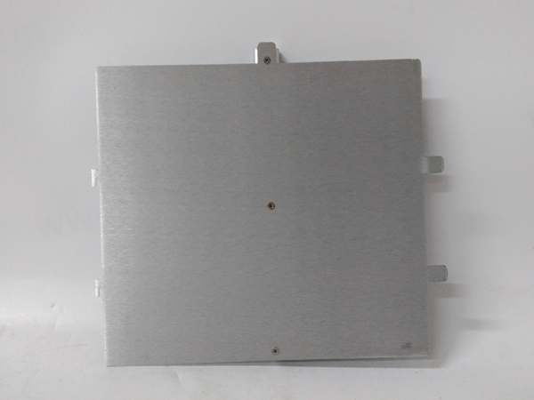
Bently Nevada 125388-01
Product Introduction
The 125388-01 is a dedicated internal baseplate adapter designed for the 3500 Machinery Protection System. It provides the mechanical mounting structure and electrical routing required to install half-height monitoring modules into standard 3500 rack frames.
This unit is a critical structural component when configuring half-height I/O or communication modules. It ensures proper alignment with the backplane connectors and maintains the required spacing for thermal management and EMI shielding within the industrial enclosure.
QA & Testing SOP (Transparency Building)
- Incoming Inspection: Verify part number 125388-01 against OEM documentation. Inspect the fiberglass substrate for micro-fractures, delamination, or heat damage. Check all gold-plated edge fingers for pitting or oxidation.
- Live Testing: Perform a dry-fit insertion into a verified 3500 test rack to confirm mechanical tolerance. Validate zero-resistance continuity across all backplane routing pins using a micro-ohm meter.
- Electrical Testing: Measure insulation resistance between adjacent signal traces (>10MΩ). Verify grounding paths and structural chassis continuity.
- Hardware Verification: Confirm the presence and condition of the matching card guide and the three required internal base screws. Inspect screw threads for stripping.
- Final QC & Packaging: Clean contact surfaces with approved solvent. Package in anti-static shielding with desiccant. Attach QC pass tag with inspection date and technician ID.
Installation Pitfalls & Guide (Engineer to Engineer)
❗ Missing Hardware Kit: This baseplate requires specific mounting hardware. Ensure you have the matching card guide (125565-01) and the three internal base screws (04300111). Missing the card guide will result in module misalignment and backplane damage.
❗ Backplane Pin Damage: The edge connector on this baseplate is highly sensitive. Never force insertion. If you feel resistance, pull it out and inspect the backplane socket for bent pins. I’ve seen entire rack slots destroyed by forcing a misaligned baseplate.
❗ Screw Torque Errors: Over-torquing the three internal base screws can crack the PCB or warp the connector alignment. Hand-tighten only, following the OEM torque spec. Under-torquing causes intermittent vibration-induced failures.
❗ Thermal Clearance Violations: Half-height modules generate heat that must exhaust properly. Ensure adjacent slots are not blocked and that the rack’s forced-air cooling is functional. Stacking too many half-high adapters without proper airflow causes thermal derating.
❗ ESD Dangers: The backplane routing traces are directly exposed. A static discharge from an ungloved hand can destroy downstream monitor modules. Always wear a grounded wrist strap when handling this bare PCB.
Replacement Guide:
- Pre-install: Document existing module configuration, verify hardware kit completeness, and ground yourself.
- Removal: Power down the rack slot. Remove the three base screws first, then extract the card guide. Pull the baseplate straight out—no prying.
- Install: Align the card guide, then slide the baseplate in with even pressure on both edges. Reinstall and snug the three screws in a cross pattern.
- Power-on Test: Insert the half-height module, verify mechanical seating, then power up. Check the 3500 System Health menu for slot communication status before returning to service.
FAQ (Frequently Asked Questions)
Q: Can I install a full-height module in this baseplate?
A: No. The 125388-01 is mechanically and electrically designed exclusively for half-height modules. Full-height modules require a different I/O module housing (e.g., 128031-01). Attempting to force a full-height module will damage both the module and the rack backplane.
Q: Is this baseplate hot-swappable?
A: Absolutely not. This is a passive backplane adapter with no hot-swap circuitry. Removing it while the rack is powered will cause an open circuit on the backplane bus, potentially corrupting data or damaging active monitor modules. Always schedule a maintenance window and de-energize the slot.
Q: Do I need to configure this baseplate in System 1 software?
A: No. The 125388-01 is a passive mechanical and electrical adapter. It has no firmware, no DIP switches, and no configurable parameters. Configuration applies only to the active half-height module installed into it.
Q: What happens if I lose one of the three mounting screws?
A: Do not substitute with generic hardware. The OEM screw (04300111) has specific thread pitch, length, and torque characteristics. Generic screws can strip the threaded insert or fail to maintain proper grounding pressure. Order the exact replacement from Bently Nevada.
Q: Can I use this baseplate in a 3300 XL rack?
A: No. The 125388-01 is engineered specifically for the 3500 series backplane pinout and mechanical dimensions. The 3300 XL uses a completely different form factor and connector standard. Cross-compatibility will result in mechanical fitment failure and electrical incompatibility.
Q: Why is my half-height module showing intermittent comm faults after installation?
A: This is almost always a seating issue. Reseat the baseplate and verify the card guide is fully engaged. Check that all three screws are properly torqued. If the problem persists, inspect the backplane socket for bent pins or debris. Vibration in rotating machinery environments amplifies marginal connections.
Q: Is this part still manufactured?
A: The 3500 system remains an active Bently Nevada product line, and this baseplate is a standard component. However, always verify current OEM availability and lead times before procurement. For legacy installations, New Original or New Surplus inventory is typically available through authorized distributors.