

Description
Hard-Numbers: Technical Specifications
- Input Channels: 16 independent temperature channels (configurable as channel pairs)
- Transducer Support:
- RTD: 100Ω platinum (DIN 43760, IEC 60751) with 2-, 3-, or 4-wire connection
- Thermocouples: Types J, K, T, E (ANSI/ASTM E230), with automatic cold junction compensation
- Temperature Measurement Range:
- RTD (2/3/4-wire): -200°C to +850°C (-328°F to +1562°F)
- Thermocouple J: -210°C to +1200°C (-346°F to +2192°F)
- Thermocouple K: -270°C to +1372°C (-454°F to +2502°F)
- Thermocouple T: -270°C to +400°C (-454°F to +752°F)
- Thermocouple E: -270°C to +1000°C (-454°F to +1832°F)
- Accuracy:
- RTD (3/4-wire): ±0.5°C at 0°C to +100°C (DIN A class), ±0.3% of full scale
- Thermocouple: ±1.5°C or ±0.75% of reading (typical)
- Input Impedance: >1 MΩ (Thermocouple), 100Ω to 10kΩ measurement range (RTD)
- Resolution: 0.1°C (RTD), 0.1°C (Thermocouple)
- Power Consumption: 4.5 watts typical
- Recorder Output: 4 to +20 mA per channel (load impedance 0-600 Ω)
- Operating Temperature: -30°C to +65°C (Standard I/O); 0°C to +65°C (Internal Barrier I/O)
- Storage Temperature: -40°C to +85°C
- Humidity: 95% non-condensing
- Update Rate: 10 samples per second per channel (default)
- Alarm Accuracy: Within 0.25% of full scale
- Compliance: EN 61000-6-2, EN 61010-1, IEC 61010-1, EMC Directive 2004/108/EC
- Barrier Parameters (Internal Barrier I/O) :
- RTD Barrier: Vmax=26.80V, Imax=112.8mA, Rmin=237.6Ω (per channel)
- Thermocouple Barrier: Vmax=27.25V, Imax=91.8mA, Rmin=297Ω (per channel)
- Dimensions: 241.3 mm × 24.4 mm × 241.8 mm (9.50 in. × 0.96 in. × 9.52 in.)
- Weight: 0.95 kg (2.10 lb) monitor module; 0.50 kg (1.10 lb) barrier I/O module
- Rack Space Requirements: 1 full-height front slot (monitor) + 1 full-height rear slot (I/O module)

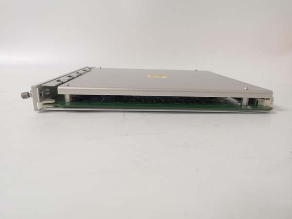
Bently 3500/60 163179-01
The Real-World Problem It Solves
You need to detect overheating bearings, stator windings, or lubrication oil before a thermal failure triggers an unplanned shutdown. This monitor provides continuous, high-resolution temperature surveillance across 16 critical points, with configurable Alert and Danger alarms that can trip your machine through relay modules. It’s the difference between a proactive temperature trending alarm and a thermal meltdown that costs millions in downtime.
Where you’ll typically find it:
- Steam and gas turbine generators in power plants, monitoring bearing temperatures on all journal bearings
- Large electric motors (HVAC, pumps, fans), tracking stator winding and bearing temperatures
- Centrifugal compressors and reciprocating compressors in gas processing, watching bearing and seal temperatures
- Hydro turbines in hydroelectric plants, monitoring thrust bearing and guide bearing temperatures
- Boiler feed pumps and cooling systems in refineries, tracking process fluid and pump bearing temps
Bottom line: This is your early-warning system for thermal problems—overheating is often the first sign of bearing wear, lubrication failure, or electrical faults, and catching it early prevents catastrophic equipment damage.
Hardware Architecture & Under-the-Hood Logic
The 3500/60 is a full-height monitor module that plugs into the 3500 rack. It communicates with the backplane for data exchange and configuration, while the rear I/O module (163179-01 with internal barriers) handles field wiring connections to RTDs and thermocouples with intrinsic safety isolation for hazardous areas. The module contains signal conditioning circuitry, cold junction compensation for thermocouples, and configurable alarm logic.
- Transducer Input: Accepts signals from up to 16 RTDs (2-, 3-, or 4-wire) or thermocouples (J, K, T, E) through the rear I/O module. Internal barrier I/O provides energy limiting for hazardous area applications.
- Signal Conditioning:
- RTD: Uses 4-wire measurement technique to compensate for lead resistance; 3-wire with compensation algorithm; 2-wire with manual compensation
- Thermocouple: Automatic cold junction compensation (CJC) using an internal thermistor at the terminal block; linearization per ISA thermocouple tables
- Measurement Processing: Computes temperature values from transducer signals with selectable filtering (1st order low-pass, 4 Hz or 20 Hz cutoff). Supports average, minimum, maximum, and difference calculations across channel pairs.
- Alarm Comparison: Compares measured temperatures against user-programmable Alert and Danger setpoints (within full-scale range). Includes alarm hysteresis (1/64 of full scale) and configurable time delays (0.1 to 60 seconds) to prevent false trips.
- Output Generation:
- Buffered BNC outputs on front panel for each channel (550 Ω output impedance, short-circuit protected) – temperature proportional to 0-5V signal
- 4-20 mA recorder outputs per channel (0-600 Ω load range)
- Digital communication via rack backplane to relay modules (3500/32, 3500/33, 3500/34) for alarm/shutdown actions
- Status Indication: Front-panel LEDs for OK, TX/RX (backplane communication), BYPASS, and per-channel status indicators

Bently 3500/60 163179-01
Field Service Pitfalls: What Rookies Get Wrong
Wrong RTD Wiring ConfigurationTechs use 2-wire RTDs on a channel configured for 4-wire measurement, then wonder why the temperature reading drifts with ambient temperature changes.
- Field Rule: Match the wiring configuration in software to the actual RTD wiring. 4-wire RTDs provide the highest accuracy (lead resistance compensation). 3-wire is acceptable for most industrial applications. 2-wire should only be used for non-critical applications or with lead compensation manually programmed. Verify by measuring lead resistance at the terminal block.
Mixing Thermocouple Types Without Updating ConfigurationReplacing a Type K thermocouple with a Type J but forgetting to change the TC type in the 3500 configuration software, causing readings to be off by hundreds of degrees.
- Quick Fix: Always verify the thermocouple type stamped on the thermocouple connector or sheath, then update the channel configuration accordingly. A Type K reading as a Type J will show approximately 60% of the actual temperature at 100°C, and the error increases exponentially at higher temps.
Ignoring Cold Junction Compensation ErrorsInstalling the temperature monitor in an environment with rapid temperature swings (e.g., outdoor cabinet without climate control), causing thermocouple readings to drift as the internal CJC sensor struggles to track terminal temperature.
- Field Rule: For thermocouple applications, install the 3500 rack in a temperature-controlled environment or use RTDs where possible. If the rack temperature varies more than ±10°C during operation, thermocouple accuracy degrades significantly. The CJC accuracy is typically ±1.5°C, but rapid changes can add additional error.
Improper Grounding of RTD ShieldsGrounding RTD cable shields at both the transducer and the monitor end, creating ground loops that introduce noise and erratic temperature readings.
- Quick Fix: Ground RTD cable shields only at the monitor end (terminal block on the rear I/O module). Leave the transducer end floating (ungrounded) or use isolated RTDs for hazardous areas. For RTDs in high-noise environments, use twisted-pair, shielded cable (Bently P/N 129526 for RTDs) and route away from power cables.
Forgetting to Adjust Alarm Hysteresis After Full-Scale ChangeChanging the temperature full-scale range from 0-200°C to 0-500°C but leaving old alarm setpoints, resulting in alarms triggering at wrong temperatures due to percentage-based setpoints.
- Field Rule: Whenever you modify the full-scale range, the rack configuration software prompts to readjust associated setpoints. Always verify and reset Alert and Danger setpoints after scaling changes. If you had Alert at 80°C (40% of 200°C) and then expand scale to 500°C, the alarm would still trip at 40% which now equals 200°C—far above your intended setpoint!
Overlooking Channel Pair ConfigurationTrying to configure all 16 channels independently instead of as channel pairs, then realizing the software forces pairing and your intended setup is impossible.
- Field Rule: The 3500/60 always configures channels in pairs (1&2, 3&4, 5&6, 7&8, 9&10, 11&12, 13&14, 15&16). Each pair can perform different functions (RTD vs. thermocouple) but the pair configuration is shared. If you need Channel 1 as RTD and Channel 2 as Thermocouple, you cannot do this—they must be the same type within the pair.
Neglecting Barrier I/O Temperature Limits in Cold ClimatesInstalling an internal barrier I/O module (163179-01) in outdoor enclosures in arctic regions where temps drop below -20°C, causing the barrier certification to void and potentially creating a hazardous condition.
- Field Rule: Internal barrier I/O modules have a minimum operating temperature of 0°C (32°F). Standard I/O modules can operate down to -30°C. In cold climates, either heat the cabinet or use standard I/O with external barriers mounted in temperature-controlled areas.
Commercial Availability & Pricing Note
Please note: The The listed price is for reference only and is not binding. Final pricing and terms are subject to negotiation based on current market conditions and availability.


