
Description
Hard-Numbers: Technical Specifications
- Display: 8-inch monochrome or color LCD (firmware dependent), 640×480 resolution typical
- Touchscreen: Resistive touchscreen (if equipped, variant dependent)
- Keypad: 12-key membrane keypad with navigation buttons
- Communication: Direct VME bus connection to rack controller (no external network)
- Display Modes: Overview screen, per-channel status, alarm history, event log, configuration screens
- Backlight: CCFL or LED backlight (variant dependent)
- Operating Temperature: 0°C to +50°C
- Storage Temperature: -40°C to +85°C
- Humidity: 5% to 95% RH non-condensing
- Power Supply: 24V DC via 3500 rack backplane
- Power Draw: 8W typical, 12W maximum with backlight at 100%
- Dimensions: Standard 3500 module form factor (12.7″ H × 17.8″ D × 3.2″ W)
- Weight: 1.5 lbs (0.7 kg)
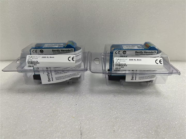
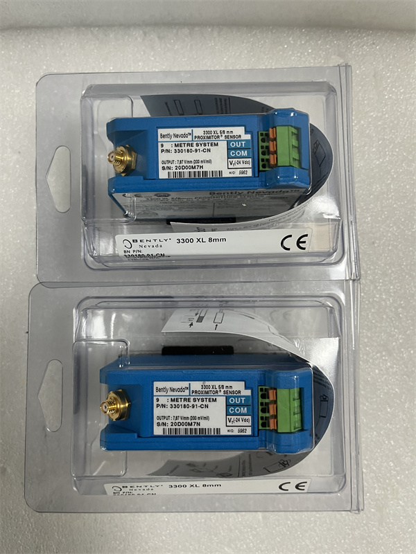
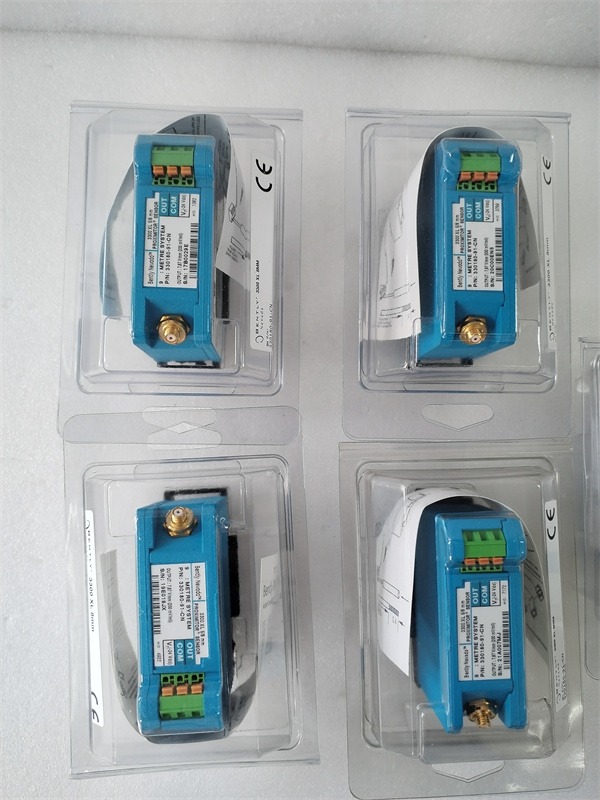
BENTLEY 330180-91-CN
The Real-World Problem It Solves
Your 3500 rack sits in a turbine hall, and the DCS operator can’t tell if an alarm is real vibration or a faulty transducer. The 3500/50-03-GCN provides local readout of all monitor channels, alarm status, and raw gap voltages so operators on the floor can diagnose issues without logging into the main control system or calling the vibration analyst.
Where you’ll typically find it:
- Turbine generator protection racks in power plants requiring local operator access
- Compressor and pump monitoring stations in refineries where floor operators need immediate alarm acknowledgment
- Machinery protection rooms where the main control system doesn’t provide detailed vibration diagnostics
Bottom line: This is the local HMI for the 3500 rack, giving floor operators a window into the protection system without needing to use a laptop or access the DCS.
Hardware Architecture & Under-the-Hood Logic
The 3500/50-03-GCN is a display and interface module that plugs directly into the 3500 VME backplane and provides a local operator interface. It contains an embedded microprocessor, graphics controller, LCD display, and keypad/touchscreen input. The module communicates directly with the rack controller via the VME bus to retrieve real-time data from all monitor modules. It operates independently from external networks, requiring only backplane power and data connections.
-
VME bus communication: The module establishes continuous communication with the rack controller (3500/20 or 3500/22) via the VME bus. It polls for updated monitor channel data, alarm status, event log entries, and configuration parameters. The rack controller pushes critical updates (trip events, bypass status) to the display module without polling.
-
Data buffering: The module buffers incoming data in RAM to ensure responsive display updates even during high event rates. Alarm states are prioritized in the display buffer to ensure immediate visual indication. Event log and historical data are stored in non-volatile memory for on-demand retrieval.
-
Graphics rendering: The embedded graphics controller renders screens for the LCD display. Screen options include rack overview (all channels with current values), per-channel detail (waveform, gap voltage, setpoints), alarm history (last 100 events), and configuration menus. The display refresh rate is typically 500 ms for real-time values.
-
User input handling: Keypad presses or touchscreen inputs are processed by the microprocessor and translated into commands for the rack controller. Supported commands include alarm acknowledgment, channel bypass, setpoint changes (if authorized), and configuration parameter viewing.
-
Display modes: The module operates in several modes:
- Normal Mode: Displays all channels with current values, alarm status, and bypass status
- Alarm Mode: Automatically switches to show active alarms when any channel enters Alarm or Danger state
- Configuration Mode: Access to setpoint viewing, channel configuration, and calibration screens (password protected)
- Event Log Mode: Displays historical alarm and trip events with timestamps
BENTLEY 330180-91-CN
Field Service Pitfalls: What Rookies Get Wrong
Not Acknowledging Alarms Before Bypassing ChannelsI’ve seen techs bypass a faulty vibration channel during maintenance to replace the transducer, but they never acknowledge the latched alarm first. The 3500/50 display shows “Danger” status even though the channel is bypassed, confusing operators about the true rack status. Worse, when they remove the bypass after repair, the old alarm is still latched and immediately trips the rack.
- Field Rule: Always acknowledge latched alarms before bypassing a channel. On the 3500/50, navigate to Alarm Mode, select the channel, and press “Acknowledge.” Verify the alarm LED extinguishes. Then proceed with bypass. Make this part of your standard maintenance procedure.
Relying Entirely on the 3500/50 for CalibrationRookie engineers perform transducer calibration using only the 3500/50 display values as reference. But the display shows rounded values (e.g., gap voltage to one decimal place) that aren’t accurate enough for precision calibration. They set gap voltage to -10.0V on the display, but actual voltage is -9.67V or -10.24V—both outside the linear range midpoint.
- Field Rule: Use the 3500 Configuration Software on a laptop for precision calibration, not the 3500/50 display. The display is for monitoring, not precision work. If you must calibrate in the field without a laptop, use a handheld multimeter to measure gap voltage at the terminal block, not the display value.
Ignoring Backlight Failure WarningsThe 3500/50 uses CCFL backlights on older variants that dim before failing completely. Techs notice the display getting harder to read but ignore it during PMs. Three weeks later, the backlight dies completely, and floor operators have no local readout until a replacement arrives. They resort to looking at the DCS trends, which don’t show raw gap voltages for diagnostics.
- Quick Fix: Check display brightness during quarterly PMs. If you notice significant dimming compared to new units, order a replacement display module or backlight service kit. If the rack is in a high-ambient-temperature environment, verify adequate ventilation around the module—heat accelerates backlight aging.
Incorrect Password Lockout During ConfigurationTechs attempt to access configuration mode on the 3500/50 and enter the wrong password three times. The module locks them out for 30 minutes (security feature) or requires a factory reset. Meanwhile, they’re supposed to acknowledge alarms and the rack is in bypass mode during this time.
- Field Rule: Keep configuration passwords documented and accessible to authorized personnel. If you’re locked out, don’t force reset—wait for the lockout timer or contact the site administrator. If you must reset, be aware that a factory reset clears all custom configuration parameters, and you’ll need to reload the configuration from backup.
Misunderstanding Displayed Values vs. Engineering UnitsThe 3500/50 displays raw gap voltage and engineering units (e.g., mils or mm) side by side. Rookie engineers read only the engineering units and don’t notice the gap voltage is pegged at -24V (probe disconnected) or saturated at 0V (probe touching the shaft). They see “0 mils” and think the measurement is correct, when in fact the probe has failed.
- Field Rule: Always check both the engineering units and the gap voltage on the 3500/50 display. Valid gap voltage for 3300/3300 XL probes should be between -2V and -18V (typically -8V to -12V at mid-gap). If voltage is at the rails, you’ve got a probe issue regardless of what the engineering units show.
Not Verifying Display Module During Rack CommissioningDuring commissioning, engineers verify all monitor modules and relay outputs but skip a full checkout of the 3500/50. They assume the display shows whatever the DCS shows. Six months later, the VME bus connection between the rack controller and the display module is intermittent due to a loose backplane pin, and the display shows frozen values from three hours ago.
- Quick Fix: Include a full 3500/50 functional test in the commissioning checklist. Verify all screens (Overview, per-channel detail, Alarm History, Event Log) are accessible. Simulate an alarm by injecting a signal and confirm the display updates correctly within the specified response time (typically <1 second). Test acknowledgment and bypass functionality.
Commercial Availability & Pricing Note
Please note: The listed price is for reference only and is not binding. Final pricing and terms are subject to negotiation based on current market conditions and availability.


