
Description
Hard-Numbers: Technical Specifications
- Input Channels: 4 independent channels (configurable as channel pairs: 1&2, 3&4)
- Transducer Support: Proximitor (displacement), Velomitor (velocity), Accelerometer (acceleration), Seismoprobe
- Input Impedance: 10 kΩ (standard I/O); 50 kΩ (TMR bussed); 150 kΩ (TMR discrete)
- Sensitivity:
- Radial Vibration: 3.94 mV/μm (100 mV/mil) or 7.87 mV/μm (200 mV/mil)
- Thrust/Shaft Absolute: 3.94 mV/μm (100 mV/mil) or 7.87 mV/μm (200 mV/mil)
- Eccentricity: 0.394 mV/μm (10 mV/mil) or 0.787 mV/μm (20 mV/mil)
- Differential Expansion: 3.94 mV/μm (100 mV/mil) or 7.87 mV/μm (200 mV/mil)
- Acceleration: 10 mV/(m/s²) (100 mV/g)
- Velocity: 20 mV/(mm/s) pk (500 mV/(in/s) pk), 5.8 mV/(mm/s) pk (145 mV/(in/s) pk), or 4 mV/(mm/s) pk (100 mV/(in/s) pk)
- Power Consumption: 7.7 watts typical
- Recorder Output: 4 to +20 mA per channel (load impedance 0-600 Ω)
- Buffered Output Impedance: 550 Ω (BNC transducer output), 300 Ω (shaft absolute output)
- Transducer Power: -24 VDC supplied by module
- Operating Temperature: -30°C to +65°C (standard I/O); 0°C to +65°C (internal barrier I/O)
- Storage Temperature: -40°C to +85°C
- Humidity: 95% non-condensing
- Frequency Response:
- Radial Vibration/Thrust/Eccentricity: 1.2 Hz to 30,000 Hz (typical)
- Acceleration: 10 Hz to 30,000 Hz (RMS), 3 Hz to 30,000 Hz (Peak)
- Velocity: 10 Hz to 5,500 Hz (RMS), 3 Hz to 5,500 Hz (Peak)
- Alarm Accuracy: Within 0.13% of desired setpoint
- Compliance: EN 61000-6-2, EN 61010-1, EMC Directive 2004/108/EC, Low Voltage Directive 2006/95/EC
- Barrier Parameters (CSA/NRTL/C & ATEX) :
- Proximitor Barrier: Vmax(PWR)=26.80V, Vmax(SIG)=14.05V, Imax(PWR)=112.8mA, Imax(SIG)=2.82mA, Rmin(PWR)=237.6Ω, Rmin(SIG)=4985Ω
- Seismic Barrier: Vmax(PWR)=27.25V, Imax(PWR)=91.8mA, Rmin(PWR)=297Ω
- Dimensions: 241.3 mm × 24.4 mm × 241.8 mm (9.50 in. × 0.96 in. × 9.52 in.)
- Weight: 0.91 kg (2.0 lb) monitor module; 0.46 kg (1.01 lb) barrier I/O module
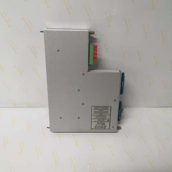
- Rack Space Requirements: 1 full-height front slot (monitor) + 1 full-height rear slot (I/O module)
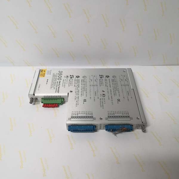
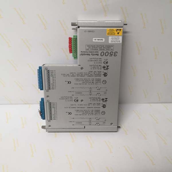
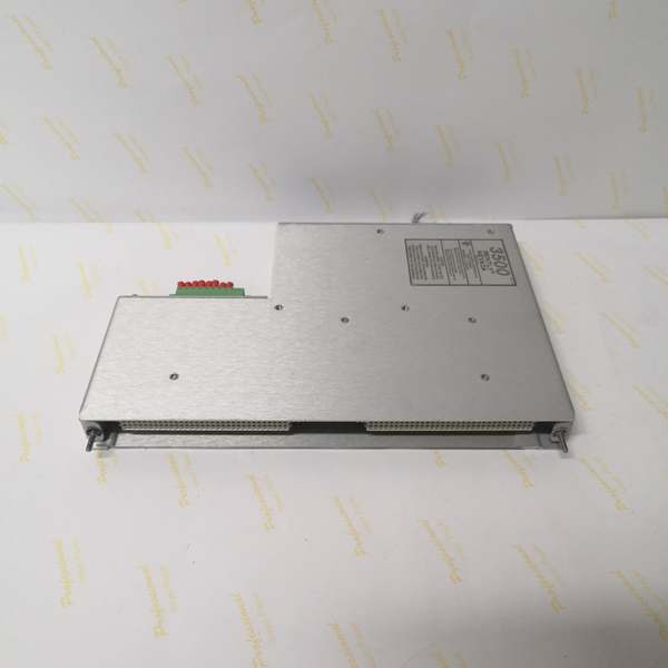
Bently 3500/42M 135489-01
The Real-World Problem It Solves
You need to catch bearing wear, shaft rub, or misalignment before it turns into a catastrophic failure. This monitor takes raw signals from displacement, velocity, and acceleration sensors, conditions them into actionable data, and trips your machine when vibration crosses safe thresholds. It’s the difference between a scheduled bearing replacement and a midnight scram with a seized rotor.
Where you’ll typically find it:
- Steam turbine generators in power plants, monitoring radial vibration on bearings and thrust position
- Centrifugal compressors in gas processing plants, tracking shaft eccentricity and differential expansion
- Boiler feed pumps and large motors in refineries, watching for acceleration spikes that indicate bearing degradation
- Hydro turbines in hydroelectric plants, measuring shaft absolute position and vibration
Bottom line: This is the eyes and ears of your machinery protection system—without accurate vibration data, you’re flying blind into a multi-million dollar equipment failure.
Hardware Architecture & Under-the-Hood Logic
The 3500/42M is a full-height monitor module that plugs into the 3500 rack. It communicates with the backplane for data exchange and configuration, while the rear I/O module (135489-01 with internal barriers) handles field wiring connections to transducers with intrinsic safety isolation for hazardous areas. The module contains signal conditioning circuitry, microprocessor-based logic, and configurable alarm setpoints.
- Transducer Input: Accepts signals from proximity transducers (displacement), velocity sensors, and accelerometers through the rear I/O module. Internal barrier I/O provides energy limiting for hazardous area applications.
- Signal Conditioning: Amplifies, filters, and conditions raw transducer signals. User-selectable filters include high-pass (4-pole, 80 dB/decade), low-pass (4-pole, 80 dB/decade), and specialized filters like gap filter (0.41 Hz -3dB) and notch filters for specific frequency bands.
- Measurement Processing: Computes proportional values including Direct, Gap, 1X Amplitude/Phase, 2X Amplitude/Phase, Not 1X Amplitude, Smax, and vector combinations depending on channel configuration.
- Alarm Comparison: Compares measured values against user-programmable Alert and Danger setpoints (0-100% of full-scale). Includes alarm hysteresis (1/64 of full scale) and configurable time delays to prevent false trips.
- Output Generation:
- Buffered BNC outputs on front panel for each channel (550 Ω output impedance, short-circuit protected)
- 4-20 mA recorder outputs per channel (0-600 Ω load range)
- Digital communication via rack backplane to relay modules (3500/32, 3500/33, 3500/34) for alarm/shutdown actions
- Status Indication: Front-panel LEDs for OK, TX/RX (backplane communication), BYPASS, and per-channel status indicators

Bently 3500/42M 135489-01
Field Service Pitfalls: What Rookies Get Wrong
Wrong Transducer-Channel Pair ConfigurationTechs configure channels 1-4 independently instead of as channel pairs (1&2, 3&4). The monitor forces channel pairing, and improper setup results in no data or incorrect measurements on channels 3 and 4.
- Field Rule: Always configure the 3500/42M in channel pairs using the 3500 Rack Configuration Software. Channels 1 and 2 are a pair; channels 3 and 4 are another pair. Each pair can perform up to two monitoring functions simultaneously (e.g., radial vibration on pair 1&2, thrust position on pair 3&4).
Missing Keyphasor Reference for Vibration ChannelsSetting up radial vibration or eccentricity channels without a Keyphasor reference, then wondering why 1X/2X amplitude and phase data show zero or “not available.”
- Quick Fix: Install a 3500/25 Keyphasor Module in the rack and configure it as the reference for vibration channels. Only Direct and Gap values are available without a Keyphasor. For 1X, 2X, and Smax measurements, the Keyphasor is mandatory.
Ignoring Barrier I/O Temperature LimitsInstalling an internal barrier I/O module (135489-01) in environments below 0°C, causing the barrier certification to void and potentially creating a hazardous condition.
- Field Rule: Internal barrier I/O modules have a minimum operating temperature of 0°C (32°F). Standard I/O modules can operate down to -30°C. In cold climates, either heat the cabinet or use standard I/O with external barriers.
Incorrect Alarm Hysteresis UnderstandingSetting alarm setpoints at the exact failure threshold, then experiencing nuisance alarms when vibration hovers around the trip point due to the 1/64 full-scale hysteresis.
- Quick Fix: Account for hysteresis when setting alarms. If full scale is 10 mils and you want to trip at 6 mils, the alarm won’t clear until vibration drops below 5.84 mils (6 – 0.16 mils hysteresis). Set danger setpoints with margin for this deadband.
Mixing Up I/O Module TypesTrying to use an internal barrier I/O module with unsupported transducer types like Seismoprobe or non-standard 2-wire accelerometers on channels configured for barrier isolation.
- Field Rule: Internal barrier I/O modules (135489 series) support Prox/Accel and Velomitor transducers. For Seismoprobe or special accelerometers, use standard I/O modules (128229-01 internal, 128240-01 external) or configure accordingly. The 3500/42M will reject incompatible I/transducer combinations.
Forgetting to Adjust Scale Factors After Full-Scale ChangeChanging the transducer full-scale range in software but leaving old alarm setpoints, resulting in alarms triggering at wrong vibration levels.
- Field Rule: Whenever you modify the full-scale range, the rack configuration software prompts to readjust associated setpoints. Always verify and reset Alert and Danger setpoints after scaling changes. The alarms are percentage-based, so changing the scale changes the absolute trip values.
Commercial Availability & Pricing Note
Please note: The listed price is for reference only and is not binding. Final pricing and terms are subject to negotiation based on current market conditions and availability.


