
Description
Hard-Numbers: Technical Specifications
- Measurement Channels: 4 independent position channels (configured as 2× differential expansion pairs or 4× independent channels)
- Transducer Support: 3300 Series, 7200 Series, or 3300 XL proximity probes (5mm or 8mm systems)
- Displacement Range: ±2 mm standard (configurable up to ±4 mm with probe selection)
- Measurement Accuracy: ±1% of full scale (±0.02 mm typical)
- DC Output: 4-20 mA per channel (proportional to measured position)
- Alert/Danger Setpoints: Software-configurable with hysteresis (typically ±2% FS)
- Bypass Capability: Manual or automatic bypass per channel
- Communication Interface: Internal VME bus to rack controller (no direct field communication)
- Isolation: 1500V RMS galvanic isolation between channels and backplane circuits
- Operating Temperature: 0°C to +50°C
- Storage Temperature: -40°C to +85°C
- Humidity: 5% to 95% RH non-condensing
- Power Supply: 24V DC via 3500 rack backplane
- Power Draw: 2.5W typical, 4W maximum
- Dimensions: Standard 3500 module form factor (12.7″ H × 17.8″ D × 3.2″ W)
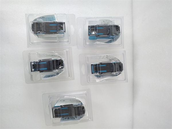
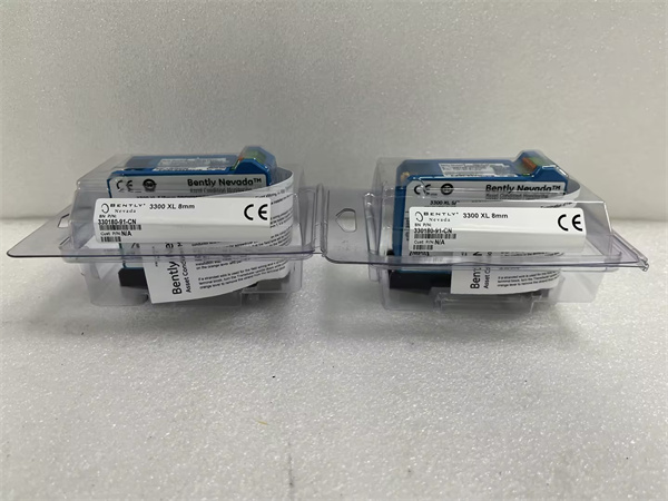
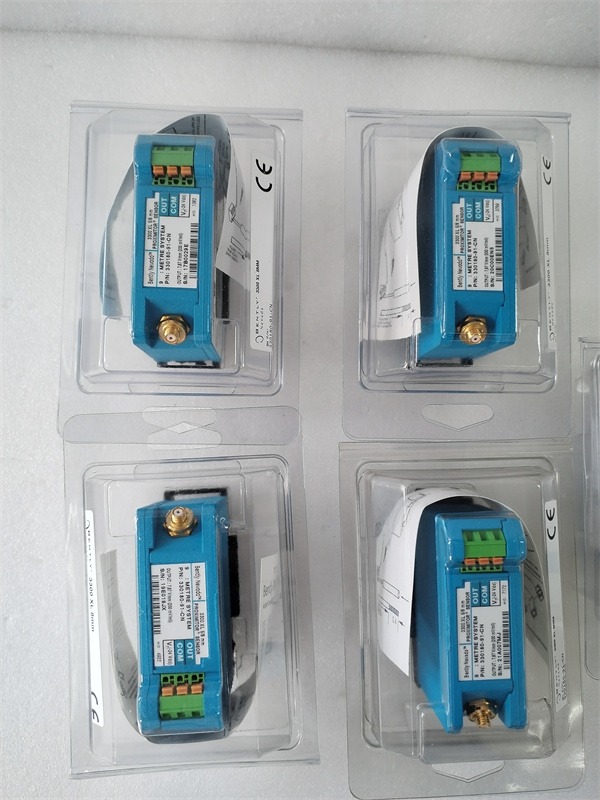
- Target: 3300 XL 5mm or 8mm probes, probe extensions, interstitial cables, and Proximitor sensors
- Weight: 0.8 lbs (0.4 kg)
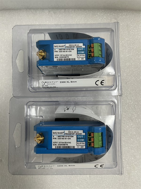
BENTLEY 330180-91-CN
The Real-World Problem It Solves
Your steam turbine’s differential expansion (differential expansion between rotor and casing) changes during startup and shutdown, and you need precise position data to prevent rotor-stator contact. The 3500/42-10-GCN gives you four channels of absolute position measurement using proximity probes, allowing you to monitor axial shaft position, differential expansion, and eccentricity with Alert and Danger setpoints wired directly into your shutdown logic.
Where you’ll typically find it:
- Steam turbine generator sets requiring axial position (thrust bearing wear) monitoring
- Single-casing and double-casing turbine differential expansion (rotor expansion vs. casing expansion) monitoring
- Axial compressor eccentricity and rotor bow monitoring during startup
Bottom line: This is the shaft position monitor for the 3500 series, providing precision axial displacement and differential expansion measurement with the same Alert/Danger trip logic as vibration monitors.
Hardware Architecture & Under-the-Hood Logic
The 3500/42-10-GCN is a 4-channel position monitor that plugs into the 3500 VME backplane and provides absolute position measurement using non-contact proximity probes. Each channel has its own signal conditioning circuit, ADC (Analog-to-Digital Converter), and comparator logic. Channels can be operated independently or paired for differential expansion measurement (Channel 1 minus Channel 2 = net expansion). Position data is transmitted via the VME bus to the rack controller for display, logging, and alarm distribution.
-
Proximitor excitation and signal reception: The module supplies -24V DC excitation voltage to external Proximitor sensors (3300/3300 XL series). Proximitor units convert probe-to-target gap voltage to a DC voltage proportional to position. The gap voltage enters the module through terminal blocks and passes through input conditioning (low-pass filtering, surge protection).
-
Gap voltage to position conversion: The DC gap voltage is digitized by a high-resolution ADC. Calibration constants stored in module memory convert the gap voltage to physical displacement (mils or mm). The module compensates for probe linearity errors and temperature effects using lookup tables.
-
Differential expansion logic: When configured for differential expansion, the module subtracts Channel 2 (casing expansion target) from Channel 1 (rotor target) to calculate net differential expansion. This subtraction is performed digitally in real time, and the result is treated as a single measured value for Alarm/Danger comparison.
-
Setpoint comparison: The converted position (or differential expansion value) is continuously compared to software-configured Alert and Danger setpoints. When measured position exceeds setpoints, the module generates alarm signals that are routed to the rack controller for distribution to relay modules and external systems.
-
Bypass and latch functions: The module supports channel bypass (manually disable alarm comparison for a specific channel) and alarm latching (alarm condition persists even after position returns to safe range until manually reset). Bypass status is reported to the rack controller and displayed on local rack displays if installed.
-
Analog output: Each channel provides a 4-20 mA DC output proportional to measured position, scaled to the configured full-scale range. This output can be used for continuous trending in DCS or separate recording systems, independent of alarm status.
BENTLEY 330180-91-CN
Field Service Pitfalls: What Rookies Get Wrong
Mixing Probe Types on Differential Expansion ChannelsI’ve seen techs install a 3300 Series probe on Channel 1 (rotor target) and a 3300 XL probe on Channel 2 (casing target) for differential expansion measurement. The two probe families have different sensitivity curves and linearity ranges. When you subtract them, the module shows differential expansion drift of 20 mils (0.5 mm) even though nothing’s actually moving.
- Field Rule: Always use identical probe families (3300 or 3300 XL) and identical Proximitor models on both channels of a differential expansion pair. If you must mix due to existing wiring, apply individual channel calibration factors to compensate for sensitivity differences, but this is a kluge—replace with matched probes during next outage.
Incorrect Thermal Expansion CompensationTechs calibrate differential expansion at ambient temperature (25°C) without accounting for different thermal expansion coefficients between the rotor and casing materials. When the turbine warms up to 400°C, the casing expansion target (mounted on steel) expands at a different rate than the rotor expansion target (mounted on steel, but the rotor material is different). You get false differential expansion readings of 30-40 mils during startup.
- Quick Fix: Establish differential expansion zero at operating temperature, not at ambient. Perform zero calibration when the machine reaches normal operating conditions (typically after 4-6 hours of run-in). Document thermal compensation factors in the commissioning report, and verify readings against casing-mounted mechanical expansion indicators.
Not Verifying Probe Gap During InstallationNew techs install proximity probes for axial position measurement but never check the mechanical gap at the probe tip. They set the gap voltage in software assuming the probe is correctly positioned at mid-gap. In reality, the probe is installed at -14V (too close) or -8V (too far), and the module runs out of linear range when the shaft actually moves.
- Field Rule: Use a mechanical feeler gauge or dial indicator to verify probe-to-target gap before energizing. Set the mechanical gap to the midpoint of the probe’s linear range (typically 40-60 mils or 1-1.5 mm for 8mm probes). Then verify the resulting gap voltage in the 3500/42 module matches the probe’s calibration curve at that gap.
Ignoring DC Drift Over TemperatureThe 3500/42 module drifts with temperature—about 1% of full scale per 20°C change in rack ambient. In a turbine hall where summer temps hit 45°C and winter drops to 5°C, that’s 2% drift (±0.04 mm on a ±2 mm range). Rookie engineers don’t compensate, and they chase phantom differential expansion problems.
- Quick Fix: Perform periodic zero checks at different ambient temperatures. If drift exceeds 1% FS, apply temperature compensation in the software or relocate the rack to a temperature-controlled environment. Document the drift curve during commissioning and use it for trending corrections.
Wiring Proximitor Excitation Without Polarity CheckTechs connect Proximitor sensors with reversed polarity, swapping +24V and common. The Proximitor still works, but the output polarity is inverted—higher gap voltage corresponds to larger physical gap instead of smaller gap. The module shows negative differential expansion when it should be positive, and your alarm logic works backwards.
- Field Rule: Verify Proximitor wiring polarity before commissioning. Use a multimeter to check that common (COM) is at 0V relative to rack ground and that +24V is positive. After energizing, insert a shim (0.1 mm feeler) between probe and target, and verify that gap voltage changes in the expected direction (voltage should drop as gap decreases for 3300/3300 XL probes).
Forgetting to Clear Alarm Latches After BypassTechs bypass a differential expansion channel during maintenance to replace a probe, perform the work, remove the bypass, and go back to service. But they don’t clear the alarm latch from the previous trip event. The module shows “Danger” alarm status even though the reading is now zero, and the DCS annunciator blinks continuously.
- Field Rule: Always clear alarm latches after removing a bypass or performing calibration. In 3500 Configuration Software, navigate to Channel Status and issue “Clear Latch” command. Verify the alarm LED on the rack front extinguishes. Make this part of your post-maintenance checkout procedure.
Commercial Availability & Pricing Note
Please note: The listed price is for reference only and is not binding. Final pricing and terms are subject to negotiation based on current market conditions and availability.


