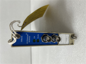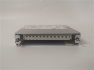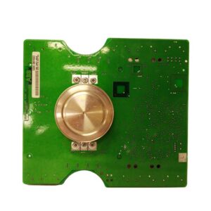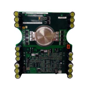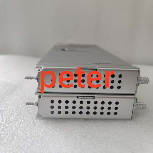
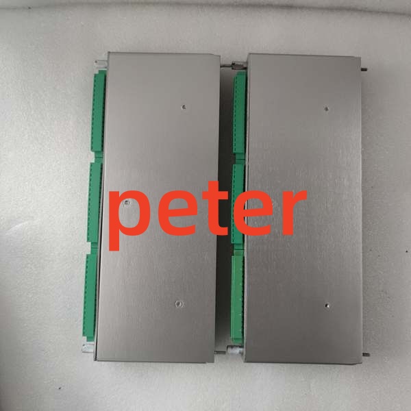
Description
Product Core Brief
- Model: 3500/33 149992-01
- Brand: BENTLY NEVADA
- Series: 3500 Machinery Protection System
- Core Function: Provides 16 independent relay outputs for machine protection trip and alarm signaling.
- Product Type: 16-Channel Relay Output Module (Spare Backplane Board)
- Key Specs: 16 Channels | Full-Height | Programmable AND/OR Logic
- Condition: New Original (New Surplus)
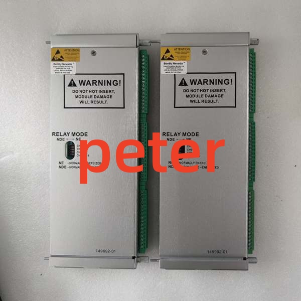
BENTLY 3500/33 149992-01
Product Introduction
The BENTLY 3500/33 149992-01 is a full-height, 16-channel relay output module designed for the Bently Nevada 3500 Machinery Protection System. It is specifically engineered to drive multiple devices or circuits, providing critical alarm and danger (trip) signals to external systems like the Emergency Trip System (ETS) or Distributed Control System (DCS).
The part number 149992-01 specifically identifies this component as the Spare 16-Channel Relay Output Module (the rear I/O backplane board). It is typically paired with the front control board 149986-01 to form the complete 3500/33-01-00 assembly. Each of the 16 relays can be independently programmed to execute specific voting logic based on inputs from any monitor channel in the rack.
Key Technical Specifications
| Parameter | Value |
|---|---|
| Module Type | 16-Channel Relay Output Module |
| Spare Board Part Number | 149992-01 |
| Channel Count | 16 Independent Relays |
| Relay Contact Rating | 25 A @ 250 VAC / 30 A @ 30 VDC |
| Module Height | Full-Height |
| Logic Programming | AND / OR Voting Logic |
| Input Sources | Any Monitor Channel in Rack |
| Typical Application | ETS Trip, DCS Alarm, Equipment Interlock |
| Compliance | API 670 |
Quality Control Process (Engineer’s Perspective)
- Incoming Verification: We check source traceability and verify serial numbers against anti-counterfeit databases. Visual inspection confirms no physical damage, bent pins, or connector corrosion.
- Live Functional Test: Power-on self-checks validate basic operation. We run continuous load tests exceeding 24 hours with temperature logging to ensure stability.
- Electrical Parameter Test: Insulation resistance is verified using a 500 V Megger, requiring >10 MΩ. Ground continuity is also strictly checked.
- Firmware Verification: We read and record internal firmware versions. DIP switch and jumper settings are photographed for future reference.
- Final QC & Packaging: The unit is sealed in an anti-static bag. A QC Passed label with the inspection date is applied before shipping.
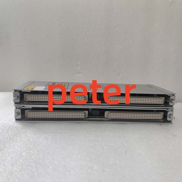
BENTLY 3500/33 149992-01
Replacement Pitfall Guide
❗ 3500/32 vs. 3500/33 Confusion: The 3500/33 is a 16-channel, full-height relay module. Do not confuse it with the 3500/32, which is a 4-channel, half-height module. They have different physical sizes and slot requirements.
❗ Front Board vs. Backplane Board: The 149992-01 is the spare output backplane board. If you are replacing a complete module assembly, ensure you also have the matching front control board (149986-01), or order the complete 3500/33-01-00 unit.
❗ Single Point of Failure Risk: Using a single 16-channel module for all critical trip signals creates a single point of failure. Industry best practice recommends utilizing redundant modules with “2-out-of-3” or “4-out-of-2” voting logic for critical machinery protection.
❗ Logic Configuration: Relay outputs are not hardwired to specific channels. You must configure the logic mapping in the 3500 configuration software before installation. An unconfigured module will not output any signals.
❗ ESD Damage: Use an anti-static mat during installation. Dry environments significantly increase electrostatic discharge risks to sensitive electronics.
Keep these in mind and you’ll cut 90% of rework time.
Compatibility Matrix & Benchmarks
- 3500/33 149992-01 → 3500/32 125720-01 : Needs Adaptation — 16-Channel Full-Height vs. 4-Channel Half-Height
- 3500/33 149992-01 → 149986-01 : Companion — Matches the 16-Channel Relay Control Module (Front Board)
- 3500/33 149992-01 → 3500/33-01-00 : Direct — Forms the complete 16-Channel Relay Module Assembly
- Max Relays per Rack: Up to 16 channels per module; multiple modules can be installed in available slots
- Companion Modules: 3500/40M / 3500/42M (M-Series Monitors providing alarm/trip inputs)