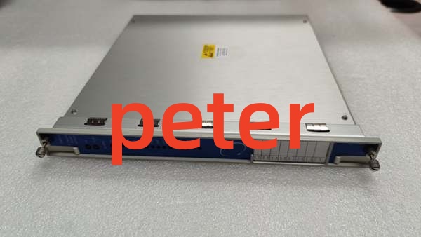
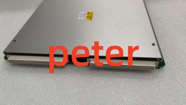
Description
Product Core Brief
- Model: 3500/33-1-00
- Brand: Bently Nevada
- Series: 3500 Machinery Protection System
- Core Function: Provides 16 independent relay outputs for machinery protection and alarm logic.
- Product Type: 16-Channel Relay Module
- Key Specs: Full-Height | 16 Relays | Independent Voting Logic | CSA/NRTL/C Certified
- Condition: New Original (New Surplus)
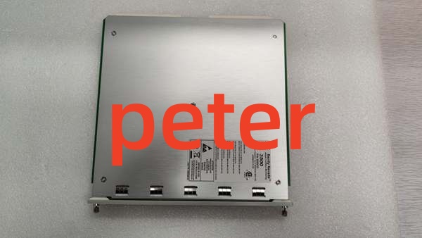
BENTLY 3500/33-1-00
Product Introduction
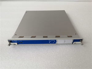
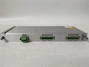
BENTLY 3500/33-1-00 is a full-height 16-channel relay module designed for the Bently Nevada 3500 Machinery Protection System. It serves as the critical output interface between the monitoring system and external plant control systems, such as Distributed Control Systems (DCS) or Emergency Trip Systems (ETS).
This module provides 16 independently programmable relay outputs. Each relay includes alarm drive logic that can be configured using AND/OR voting logic based on alarm inputs (Alert/Danger), Not-OK states, or individual measured variables from any monitor channel in the rack. The 3500/33-1-00 modules are typically installed in any available slot to the right of the Transient Data Interface (TDI) module.
Key Technical Specifications
- Module Type: 16-Channel Relay Output Module
- Form Factor: Full-Height
- Relay Count: 16 Independent Relay Outputs
- Logic Programming: AND/OR voting logic via 3500 Rack Configuration Software
- Logic Inputs: Alarm inputs (Alert/Danger), Not-OK status, individual measured variables
- Slot Placement: Any slot to the right of the Transient Data Interface (TDI) module
- Software Requirements: 3500 Rack Config v3.3+, Data Acquisition v2.40+, Data Display v1.40+
- Certifications: CSA/NRTL/C (Approval Option -01)
- Dimensions (H x W x D): 241 mm x 24.4 mm x 99.1 mm
- Weight: 0.4 kg
Quality Control Process (Engineer’s Perspective)
- Incoming Verification: Trace source via serial number. Inspect rear Euro-connector pins and front panel indicator LEDs.
- Visual Inspection: Verify relay physical condition and check for any PCB corrosion or flux residue.
- Live Functional Test: Install in rack. Verify “OK” LED illuminates and communication with RIM/TDI is established.
- Logic & Relay Test: Use 3500 Rack Configuration Software to force individual relay states. Verify audible click and continuity across relay contacts.
- Final QC & Packaging: Seal in anti-static bag. Apply QC Passed label with date.
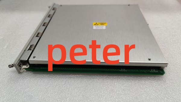
BENTLY 3500/33-1-00
Replacement Pitfall Guide
❗ Software Version: The 3500/33-1-00 requires 3500 Rack Configuration Software version 3.3 or higher. Ensure your configuration software is updated before attempting to program relay logic.
❗ Slot Placement: This module must be placed to the right of the Transient Data Interface (TDI) module. It cannot be placed in the leftmost slots reserved for power or RIM/TDI.
❗ Voltage Restrictions (Zone 2/SIL): If the module is ordered with multiple certification options (e.g., Zone 2, ATEX, or SIL), the maximum allowable voltage is restricted (e.g., 30 Vrms for CSA). Using higher voltages will violate hazardous area certificates and SIL functional safety requirements.
❗ Single Point of Failure Risk: In critical turbine protection applications, relying on a single 3500/33-1-00 module for trip signals violates “2oo3” or “4oo2” redundancy standards. Best practice requires splitting trip signals across multiple independent relay modules to prevent a single module failure from causing a false trip.
❗ Logic Configuration: Relay outputs do not function automatically. Every relay channel must be explicitly programmed with alarm drive logic using the 3500 Rack Configuration Software.
Keep these in mind and you’ll cut 90% of rework time.
Compatibility Matrix & Benchmarks
- 3500/33-1-00 → 3500/32M : Complementary — 4-Channel Relay Module (often used for lower channel count outputs)
- 3500/33-1-00 → 3500/22M : Complementary — Must be placed to the right of the TDI module
- 3500/33-1-00 → 3500/42M : Complementary — Receives alarm/trip logic from vibration monitors
Benchmarks:
- Relay Response Time: < 50 ms (typical)
- Logic Processing: Hardware-level AND/OR gate execution