
Description
Hard-Numbers: Technical Specifications
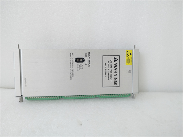
- Relay Channels: 16 independent Form C (SPDT) relays in four groups of four
- Group Configuration: Each group of 4 relays shares a common alarm voting logic source (or can be individually addressed depending on firmware revision)
- Contact Rating: 5A resistive at 250V AC / 30V DC, 0.25A inductive at 250V AC / 30V DC
- Contact Material: Silver alloy (AgNi) with gold plating for low-level signals
- Coil Voltage: Internally supplied from 3500 rack backplane (24V DC)
- Isolation: 1500V RMS galvanic isolation between relay contacts and backplane circuits
- Contact Life: Mechanical: 10⁷ operations minimum; Electrical: 10⁵ operations at rated load
- Operating Temperature: 0°C to +50°C
- Storage Temperature: -40°C to +85°C
- Humidity: 5% to 95% RH non-condensing
- Power Supply: 24V DC via 3500 rack backplane
- Power Draw: 4W typical (coils de-energized), 8W maximum (all coils energized)
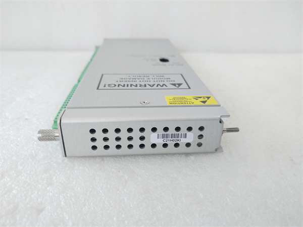
- Dimensions: Standard 3500 module form factor (12.7″ H × 17.8″ D × 3.2″ W)
- Weight: 1.2 lbs (0.5 kg)
Bentley 128229-01
The Real-World Problem It Solves
You’ve got a massive compressor train with 12 vibration monitors, two axial position monitors, and each one needs both Alert and Danger contacts wired to the DCS, ESD, and local annunciator panel. That’s 42 dry contacts minimum, and you don’t have space for ten 3500/32 modules. The 3500/33-03-GCN gives you 16 relay outputs in one slot, so you can wire all your alarm logic without filling the entire rack with relay modules.
Where you’ll typically find it:
- Large turbomachinery trains (steam turbines, gas compressors) with multiple bearing monitors requiring extensive alarm and trip contact distribution
- Refinery and petrochemical units where multiple protection levels (alert, pre-trip, trip) must be signaled to separate safety systems
- Centralized machinery protection rooms where annunciator panels require individual contact per monitor
Bottom line: This is the high-density relay module for big protection racks, packing 16 Form C outputs into a single slot so you’re not burning half your rack space on relay modules.
Hardware Architecture & Under-the-Hood Logic
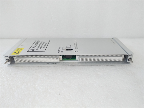
The 3500/33-03-GCN is essentially four 3500/32-style relay modules crammed into one physical module. It contains 16 electromechanical Form C relays organized into four groups of four channels each. The module plugs into the 3500 VME backplane and receives alarm status from monitor modules via internal communication. Each group can be configured to respond to specific monitor alarm states, and each of the 16 relay channels operates independently with its own logic programming. Relays are driven from the internal 24V supply, and contact wiring terminates on a dual-row removable terminal block.
-
Backplane communication: The module continuously polls alarm status from up to 16 monitor modules via the VME bus. The 3500 Configuration Software assigns each of the 16 relay channels to specific monitor alarms (Alert, Danger, Not OK, or combinations). Firmware supports both channel-to-monitor mapping and group-based logic where all four relays in a group respond to the same alarm condition.
-
Logic evaluation: The onboard microprocessor evaluates incoming alarm status against programmed logic for each of the 16 relay channels. Logic options include direct alarm mapping, AND/OR combinations, voting logic (1oo1, 1oo2, 2oo3), and time delays. The four-group architecture allows you to segment logic—for example, Group 1 handles compressor bearing alarms, Group 2 handles turbine alarms, Group 3 handles axial position, and Group 4 handles overspeed or external inputs.
-
Coil drive: When logic conditions are met for any channel, the microprocessor energizes that channel’s relay coil through an internal transistor driver circuit. The module can energize any combination of the 16 coils simultaneously. Each channel has an LED indicator showing coil state, and the module provides status LEDs for each group to quickly identify which relay group is active.
-
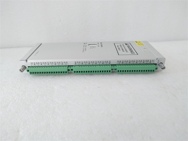
Contact output: Energizing the coil moves the relay armature, changing contact state. Each channel provides Form C (SPDT) contacts: Common (C), Normally Open (NO), and Normally Closed (NC). When de-energized, C is connected to NC; when energized, C switches to NO. All 16 channels are galvanically isolated from backplane electronics and from each other, preventing ground loops between different external systems.
-
Arc suppression and group protection: The module includes configurable snubber circuits for inductive loads. Snubbers can be enabled per-group or per-channel depending on firmware revision. Each relay channel has overcurrent protection, and the module monitors relay contact health. Stuck-weld detection can identify failed relays, though this requires firmware support and external monitoring circuitry.
Bentley 128229-01
Field Service Pitfalls: What Rookies Get Wrong
Mixing High and Low-Voltage Loads on Same ModuleI’ve seen techs wire the first four relays to 24V DC ESD inputs and the next four to 120V AC annunciator lights. Sure, the contact ratings support both, but now you’ve got 120V AC routing through the same terminal block as low-voltage safety circuits. One wiring mistake or insulation failure, and your ESD system sees 120V AC on a 24V input—bad news for safety-rated inputs.
- Field Rule: Segregate voltage levels on separate relay modules when possible. If you must mix voltages on the 3500/33, keep high-voltage AC wiring on one side of the terminal block and low-voltage DC on the other. Use physical separation or terminal barriers, and clearly label terminal numbers with voltage levels.
Running 16 Coils Simultaneously Overheats the ModuleRookie engineers assume the 8W maximum power draw covers all operating conditions. But in real-world trips, you can have all 16 relays energized at once during full alarm storms. The internal 24V supply has to drive 16 coils plus logic circuitry, and the module heats up. In hot climates with poor rack ventilation, the module enters thermal derating and relays start sticking or failing to energize.
- Quick Fix: Verify the rack’s internal power supply can handle the full load of all relays energized simultaneously. The 3500 rack has a 40W power budget limit per rack. If you’re running multiple 3500/33 modules, calculate worst-case coil power. Add rack ventilation fans if ambient temps exceed 40°C.
Not Understanding Group vs. Individual Channel ConfigurationFirmware revisions vary on how the 3500/33 handles configuration. Some older versions force all four relays in a group to follow the same logic source—you can’t have Relay 1 follow Monitor 1 and Relay 2 follow Monitor 2 if they’re in the same group. Rookie engineers waste hours trying to program individual logic before realizing their firmware doesn’t support it.
- Field Rule: Check your firmware revision before planning alarm-to-relay mapping. Older firmware supports group-based logic only; newer revisions support channel-individual mapping. If you need per-channel flexibility and have old firmware, either upgrade firmware or plan your monitor-to-relay assignments around the four-group structure.
Terminal Block Crowding and Wiring ErrorsThe 3500/33 has 48 contact connections plus coil power and commons—all on one dense terminal block. I’ve seen techs mix up C, NO, and NC terminals when rushing to commission a rack. They wire a DCS input to NC instead of NO, and the alarm logic works backwards—alarm clears when it should trip, and trips when it should clear.
- Quick Fix: Use a wiring template or pre-made terminal label template before pulling wires. Map each channel’s C/NO/NC terminals on paper before touching a screwdriver. Verify each connection with a continuity tester after wiring. Color-code your field wiring (e.g., black for Common, red for NO, white for NC) to reduce errors.
Forgetting Snubber Configuration on Half the RelaysTechs enable snubbers on Group 1 (relays 1-4) driving inductive loads, but forget Groups 2-4 because those were added later or reconfigured. Six months later, a solenoid valve on Relay 8 welds the contacts, and nobody realized snubbers weren’t enabled on that channel.
- Field Rule: Document snubber configuration per channel in your commissioning checklist. Any time you add or reconfigure a load, verify snubber status in configuration software. If a channel drives anything inductive (solenoid, contactor coil, motor starter), enable the snubber—no exceptions.
Relay Contact Welding on High-Cycle ApplicationsThe 10⁵ electrical life rating is for resistive loads at full current. If you’re driving small 24V DC pilot lights that cycle on/off continuously for process indication, you’ll exceed the life rating fast. I’ve seen relays in the 3500/33 fail after two years of continuous 1-second cycling in a boiler feedwater pump application.
- Field Rule: For high-cycle applications (more than 10 cycles per minute continuous), consider using solid-state relays or interposing relays external to the 3500 rack. Use the 3500/33 contacts to drive the interposing relay coil, not the high-cycle load directly. This protects the expensive 3500 relay module from wear.
Commercial Availability & Pricing Note
Please note: The listed price is for reference only and is not binding. Final pricing and terms are subject to negotiation based on current market conditions and availability.


