


Description
Hard-Numbers: Technical Specifications
- Relay Configuration: 4 channels, Two SPDT relays per channel connected as DPDT
- Maximum Switching Voltage: 250 VAC / 125 VDC (standard system); 30 VAC/VDC (SIL/hazardous)
- Maximum Switching Current: 5A resistive load; DC varies by voltage (2A @ 0-30VDC, 0.75A @ 48VDC, 0.2A @ 125VDC)
- Maximum Switching Power: DC: 120W; AC: 600VA
- Response Time: <10 ms (input signal to relay actuation)
- Operating Voltage: +5 VDC (from 3500 rack backplane)
- Power Consumption: 5.8W typical
- Operating Temperature: -30°C to +65°C (-22°F to +149°F)
- Storage Temperature: -40°C to +85°C (-40°F to +185°F)
- Humidity: 95% non-condensing
- Contact Life: 100,000 operations @ 5A, 24VDC or 240VAC
- Compliance: UL 508, IEC 61508 (SIL 2), ATEX, cNRTLus (Class I, Zone 2 options available)
- Dimensions: 241 mm x 24.4 mm x 242 mm (9.50 in. x 0.96 in. x 9.52 in.)
- Weight: 0.7 kg (1.6 lb.)
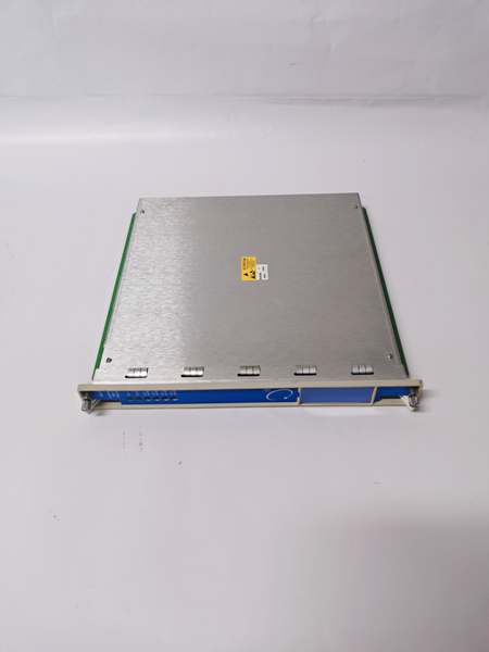
Bently Nevada 3500/32 125712-01
The Real-World Problem It Solves
You’ve got vibration, temperature, and speed monitors screaming at the DCS, but the plant needs hard, relay-based shutdowns that don’t rely on software. This module takes those digital signals and slams real contacts closed—fast enough to save a turbine before a rotor rub turns into a $2M repair. No more waiting for network latency or software glitches to kill your machine.
Where you’ll typically find it:
- Steam turbine protection loops in coal-fired power plants, paired with 3500/42M vibration monitors
- Centrifugal compressor safety systems in refineries, driving ESD valves on high-vibration trips
- Gas pipeline pump skids, triggering shutdowns when bearing temps exceed safe limits
Bottom line: This is the final link between your monitoring system and the big red button—when it matters most, you need metal contacts, not Ethernet packets.
Hardware Architecture & Under-the-Hood Logic
The 3500/32 is a full-height module that plugs into any slot right of the Rack Interface Module. It pulls power and trigger signals from the backplane, no external power needed. Each relay channel is a self-contained DPDT switch with its own coil and contacts, isolated from the others to prevent cross-talk.
- Signal In: Receives alarm/danger signals from 3500 monitor modules (vibration, position, speed) via the backplane.
- Logic Processing: Applies user-configured AND/OR voting logic (set via 3500 Rack Configuration Software).
- Relay Actuation: Coil energizes/de-energizes within 10ms, flipping both poles of the DPDT contact.
- Status Feedback: Front-panel LEDs for OK (module healthy), TX/RX (backplane comms), and per-channel alarms.
- Isolation: All relay contacts are electrically isolated from the backplane to prevent ground loops in field wiring.

Bently Nevada 3500/32 125712-01
Field Service Pitfalls: What Rookies Get Wrong
Wiring Normally Open vs. Normally Closed ContactsNew techs wire shutdown circuits to NC contacts instead of NO. During a fault, the relay de-energizes, contacts open, and nothing happens—until the turbine grenades.
- Field Rule: For safety shutdowns, use Normally Open contacts. Relay energizes on alarm, closing the circuit to trip the breaker. Verify with a multimeter in “diode test” mode before power-up.
Overloading Relay ContactsInstalling 10A solenoids on 5A relays. The contacts weld closed after a few cycles, leaving you with a stuck-on relay and a very expensive paperweight.
- Quick Fix: Never exceed 5A resistive load. For inductive loads (motors, solenoids), derate to 25% of rating (1.25A max). Use an external contactor if higher current is needed.
Ignoring Contact ProtectionNo surge suppression on inductive loads. The voltage spike when the relay opens arcs across the contacts, burning them out in months.
- Field Rule: Install MOVs or RC snubbers across relay outputs when switching motors, valves, or solenoids. Bently recommends 0.1µF capacitor + 100Ω resistor in parallel for DC circuits.
Forgetting Relay Reset LogicProgramming latching alarms without a reset path. After a trip, the relay stays energized even after the fault clears, requiring a manual reset—bad news if it’s 2 AM and the plant’s down.
- Field Rule: Use the 3500 software to configure “Auto-Reset” for non-critical alarms. For shutdowns, program a reset signal from the operator interface or a hardwired reset button.
Mismatched Logic PolarityMixing “energize on alarm” and “de-energize on alarm” channels. Half the relays trip on fault, half don’t—you’ll spend hours tracing wiring when the system fails to respond.
- Field Rule: Standardize on “energize on alarm” for all critical channels. Label the terminal block with polarity and function (e.g., “CH1: Turbine Trip – NO Energizes on Danger”).
Commercial Availability & Pricing Note
Please note: The listed price is for reference only and is not binding. Final pricing and terms are subject to negotiation based on current market conditions and availability.

