
Description
Hard-Numbers: Technical Specifications
- Input Channels: 2 isolated Keyphasor inputs (independent)
- Transducer Types Supported: Proximity probes (non-contact), Magnetic pickups (speed pickup), Optical sensors, Hall-effect sensors
- Input Impedance: 10 kΩ (typical for proximity probes)
- Trigger Threshold: Software-configurable (typically -10 to +10 V for proximity)
- Frequency Range: 0 to 20 kHz (depending on transducer)
- Output Signals: TTL-compatible pulse outputs, Buffered Keyphasor signal (BKPY)
- Isolation Rating: 1500V RMS galvanic isolation between inputs and backplane
- Operating Temperature: 0°C to +50°C
- Storage Temperature: -40°C to +85°C
- Humidity: 5% to 95% RH non-condensing
- Power Supply: 24V DC via 3500 rack backplane
- Power Draw: 1.5W typical
- Dimensions: Standard 3500 module form factor (12.7″ H × 17.8″ D × 3.2″ W)
- Weight: 0.8 lbs (0.4 kg)
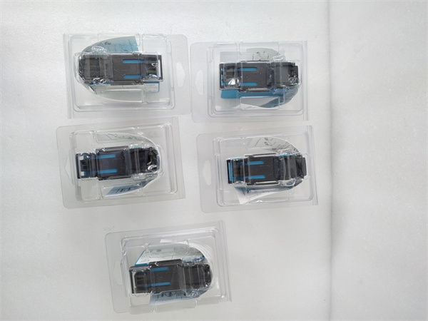
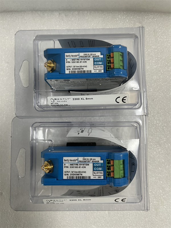
BENTLEY 330180-91-CN
The Real-World Problem It Solves
Your vibration data is just amplitude noise without a phase reference—you can’t tell if you’re looking at 1× running speed or subsynchronous instability, and you certainly can’t generate meaningful orbit plots. The 3500/25-02-GCN locks the 3500 system’s sampling to the actual shaft rotation, giving you phase-accurate vibration data and enabling time waveform analysis synchronized to shaft speed.
Where you’ll typically find it:
- Steam turbine generator sets requiring phase reference for balance and alignment analysis
- Centrifugal compressor trains where subsynchronous vibration (oil whirl/whip) diagnosis is critical
- Machinery protection systems in paper mills and steel rolling mills needing precise orbit plots and shaft centerline data
Bottom line: This is the timing heart of the 3500 system, converting once-per-revolution shaft targets into synchronized trigger pulses that make vibration data meaningful for diagnostics and protection.
Hardware Architecture & Under-the-Hood Logic
The 3500/25-02-GCN is a dual-channel Keyphasor module that sits on the 3500 VME backplane and provides phase reference signals to all other monitor modules in the rack. Each channel has its own input conditioning circuit, threshold detector, and pulse generator. The module continuously monitors shaft position transducers and generates digital pulse outputs synchronized to physical shaft rotation. Both channels are galvanically isolated from each other and from the backplane.
-
Signal conditioning: Raw Keyphasor transducer signals (proximity probe voltage, magnetic pickup sine wave, or optical pulses) enter the module through terminal blocks. Input circuitry filters noise, limits voltage, and amplifies weak signals. For proximity probes, the module supplies DC excitation voltage (-24V) through the same connection.
-
Threshold detection: The converted signal passes through a software-configurable comparator. You set the trigger threshold voltage (e.g., -10V for a proximity probe crossing the gap voltage midpoint). When the input crosses this threshold, the detector fires a digital trigger event.
-
Pulse generation: Each trigger event generates a TTL-compatible output pulse (typically 5V logic level). The module produces two output types per channel: a raw pulse for direct monitor triggering and a buffered Keyphasor (BKPY) signal distributed across the backplane to all monitor modules in the rack.
-
Backplane synchronization: The BKPY signals are distributed via the 3500 internal timing bus. Monitor modules (3500/40M, 3500/42M, etc.) use these pulses as sampling triggers, ensuring all vibration channels sample at the same physical shaft position every revolution. This enables synchronous averaging and phase-locked time waveform capture.
-
Status monitoring: The module continuously monitors input signal health. It detects loss of signal (no pulses for a configurable timeout period), erratic signal (multiple pulses per revolution), or signal stuck high/low. Fault status is reported to the Interface Module and can trigger rack alarms.
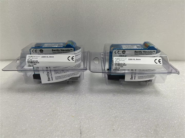
BENTLEY 330180-91-CN
Physical Wiring and Transducer Compatibility
Keyphasor Transducer Options
- Proximity Probes: Most common in turbomachinery. The probe observes a physical target (key, bolt, or keyway) on the shaft. Requires -24V DC excitation from the module. Output is a voltage swing from -24V to near 0V as the target passes.
- Magnetic Pickups: Passive speed sensors used in gear-driven machinery. Generate AC sine wave voltage proportional to speed (typically 1–30V AC). No excitation required.
- Optical/Hall Sensors: Active sensors requiring external power. Output digital pulses directly. Less common in harsh environments but used where mechanical targets aren’t feasible.
Target Configuration
- Single bolt or keyway: 1 pulse per revolution (1 PPR)
- Gear teeth: Multiple pulses per revolution (requires module configuration to avoid over-triggering)
- Phased multiple targets: Used for torsional vibration analysis or angular position reference
Wiring and Shielding
- Use twisted shielded pair cables for all Keyphasor signal wiring
- Connect shield at rack end only to avoid ground loops (single-point grounding)
- Keep Keyphasor wiring separated from high-voltage power cables by at least 12 inches
- Use proper conduit for routing through hazardous areas
Field Service Pitfalls: What Rookies Get Wrong
Wrong Threshold Setting on Proximity Probe SystemsI’ve seen rookie engineers set the trigger threshold at -5V on a system where the probe’s gap voltage is -10V and swings to -2V over the target. The trigger fires halfway through the target pass, giving inconsistent phase data and jittery orbit plots. Even worse, they set it too close to the gap voltage and get false triggers from runout or electrical noise.
- Field Rule: Set the threshold midway between the minimum and maximum voltage swing. Use a handheld vibration analyzer or oscilloscope to observe the actual Keyphasor waveform at the module input terminals before configuring. Verify consistent trigger timing over multiple revolutions.
Multi-Tooth Gear Over-TriggeringTechs replace a single-bolt Keyphasor with a gear tooth pickup for higher speed resolution, but forget to reconfigure the module for multi-pulse operation. The module fires on every tooth pass, confusing the monitor’s once-per-revolution logic. Result: scrambled phase data and completely useless orbit plots.
- Quick Fix: Verify target configuration matches physical reality. If you’re using a gear tooth sensor, configure the module for the correct teeth count or use a hardware divider/skipping circuit to output 1 PPR. When in doubt, stick to a single physical target—it’s foolproof.
Loose Target or Runout Masking Real VibrationA target bolt works loose or gets covered in grease buildup. The Keyphasor signal now varies from revolution to revolution, and your phase data drifts all over the place. Rookie engineers chase phantom vibration problems because the reference itself is unstable.
- Field Rule: Inspect Keyphasor targets during every PM. Verify bolts are torque-sealed and the target area is clean. Measure gap voltage with the shaft at rest—it should be stable within ±0.5V. If you see variation, you’ve got mechanical runout or a loose target.
Ground Loops and Stray ShieldingTechs ground both ends of the shielded Keyphasor cable to “be safe.” This creates a ground loop, and 50/60 Hz hum rides on the Keyphasor signal. The threshold detector fires erratically, and your BKPY pulse train turns into noise.
- Quick Fix: Ground shields at the rack end only. Use single-point grounding at the 3500 terminal block. If you must shield at the transducer end (hazardous area), use an isolated barrier or signal conditioner. Never connect the shield to both the sensor housing and the rack ground.
BKPY Signal Loss to MonitorsThe buffered Keyphasor (BKPY) signal routes through the rack backplane to all monitor modules. I’ve seen techs populate a monitor in a slot that doesn’t receive BKPY timing from the 3500/25, or install a newer monitor module that requires explicit BKPY routing configuration in software. Result: phase data disappears, and orbit plots become random dots.
- Field Rule: Verify every monitor requiring phase reference is physically connected to receive BKPY (check rack slot backplane routing). In 3500 Configuration Software, ensure BKPY distribution is enabled to the correct monitor addresses. Test by forcing a manual Keyphasor pulse and verifying all monitors update simultaneously.
Ignoring Speed Range During CalibrationYou calibrate the Keyphasor at low speed (500 RPM) during commissioning, but the machine runs at 15,000 RPM. At high speed, magnetic pickup signal amplitude drops or rises beyond the module’s input range. The module 终止s triggering, and you lose all phase-locked protection just when you need it most—during high-speed operation.
- Quick Fix: Test Keyphasor signal amplitude across the entire operating speed range during commissioning. Use a variable frequency drive to sweep from minimum to maximum speed. Verify the module maintains consistent triggering at 110% of max continuous speed. If signal drops below 1V at high speed, swap in a higher-sensitivity pickup.
Commercial Availability & Pricing Note
Please note: The listed price is for reference only and is not binding. Final pricing and terms are subject to negotiation based on current market conditions and availability.


