
Description
Hard-Numbers: Technical Specifications
- Dimensions:
- Internal Barrier Earthing Module (136719-01): 241.3 mm × 24.4 mm × 103.1 mm (9.50 in × 0.96 in × 4.06 in)
- Internal Barrier I/O Modules (e.g., 135489-01/02/03/04, 136703-01, 136711-01/02, 137110-01): 241.3 mm × 24.4 mm × 163.1 mm (9.50 in × 0.96 in × 6.42 in)
- Weight:
- Earthing Module (136719-01): ~0.46 kg (1.01 lb)
- Internal Barrier I/O Modules: ~0.46 kg (1.01 lb)
- Approvals (per datasheet/approvals quick reference guide 108M1756):
- CSA/NRTL/C: Class I, Zone 2 (AEx nA/nC ic IIC T4 Gc; AEx ec nC ic IIC T4 Gc); Class I, Division 2, Groups A, B, C, D
- ATEX/IECEx: Class I, Zone 2; T4 @ Ta = -20°C to +65°C (-4°F to +149°F) when installed per drawing 149243/149244
- CE/EMC: EN 61000-6-2, EN 61000-6-4; EN 55011 Class A; Electrical Safety EN 61010-1; LVD 2014/35/EU
- RoHS 2011/65/EU
- ABS (marine/offshore per DNV GL rules)
- Environmental:
- Operating Temperature: 0°C to +65°C (+32°F to +149°F)
- Storage Temperature: -40°C to +85°C (-40°F to +185°F)
- Humidity: 95% non-condensing
- Electrical Ratings (per entity parameters in datasheet):
- Proximity & Acceleration (applies to Aero/DP with mods):
- Bandwidth: 30 kHz
- Amplitude Accuracy: 3% @ 10 kHz; -15/+10% @ 30 kHz
- Phase Accuracy: -11° @ 10 kHz
- Channel Parameters (Um = 250 V): Uo = 27.45 V; Io = 113.24 mA; Co = 0.086 µF; Lo = 2.77 mH; Po = 726.96 mW
- Circuit Power (PWR): Uo = 26.25 V; Rmin = 237.6 Ω; Io = 110.48 mA
- Circuit Signal (SIG): Uo = 13.65 V; Rmin = 4985 Ω; Io = 2.74 mA
- Velomitor:
- Amplitude Accuracy: ±1%
- Circuit: Uo = 26.25 V; Rmin = 297 Ω; Io = 88.39 mA
- Channel Parameters: Um = 250 V; Uo = 26.25 V; Io = 88.39 mA; Co = 0.097 µF; Lo = 4.55 mH; Po = 580.02 mW
- Temperature:
- Temperature Accuracy: ±1°C @ +25°C; ±15°C over operating temperature
- Phase Accuracy: -11° @ 10 kHz
- Channel Parameters: Um = 250 V; Uo = 7.71 V; Io = 89.17 mA; Co = 9.3 µF; Lo = 4.55 mH; Po = 132.41 mW
- Circuit B: Uo = 5.36 V; Rmin = 133.25 Ω; Io = 40.23 mA
- Circuit C: Uo = 6.51 V; Rmin = 133.25 Ω; Io = 48.86 mA
- Process Variable:
- Channel Parameters: Um = 250 V; Uo = 27.98 V; Io = 279.34 mA; Co = 0.083 µF; Lo = 0.455 mH; Po = 842.89 mW
- Circuit Power (PWR): Uo = 26.78 V; Rmin = 297 Ω; Io = 90.17 mA
- Circuit Signal (SIG): Uo = 9.56 V; Rmin = 50.58 Ω; Io = 189.01 mA
- Proximity & Acceleration (applies to Aero/DP with mods):
- Cabinet Fit:
- Standard 19-inch rack with internal barrier modules fits comfortably into 600 mm cabinets; bulkhead rack version available for cabinets with top/bottom bulkhead separation
- When any internal barrier module is used, the rack is limited to a maximum of 13 monitor positions (IS Earthing Module consumes a dedicated slot)
- Internal Barrier I/O modules increase rack depth by approximately 50 mm (2 in) to maintain the 50 mm physical separation between hazardous area and safe area wiring
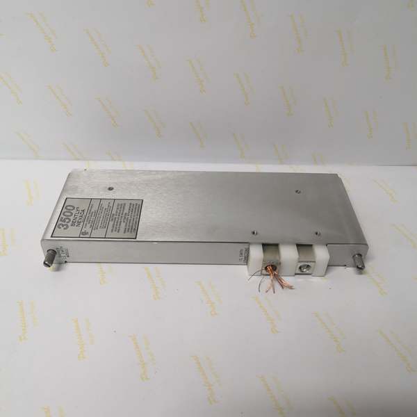
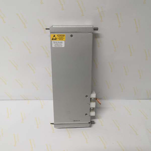
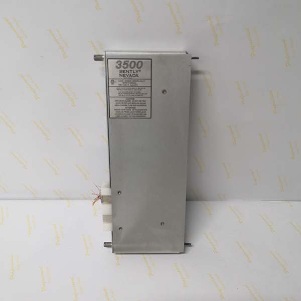
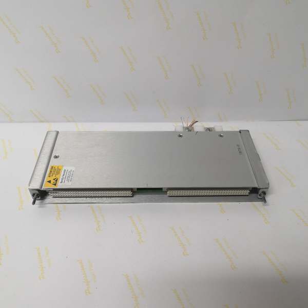
BENTLY 3500/04 136719-01
The Real-World Problem It Solves
Hazardous area installations (e.g., oil & gas, petrochemical, offshore platforms) require intrinsic safety protection for field wiring. Traditional external safety barriers between the transducer and monitor add bulk, wiring complexity, and potential signal degradation. 3500 Internal Barriers integrate the IS interfaces directly into the I/O modules, eliminating external barriers while maintaining full compatibility with the 3500 system. The 136719-01 IS Earthing Module is mandatory in any rack containing Internal Barrier I/O modules because it provides the intrinsically safe earth connection through the rack backplane. Without it, the barrier circuits lack a proper safety earth, violating certification and creating a hazard. The design groups all IS I/O modules together for simplified hazardous-area wiring routing (wires above rack, safe-area wires below rack), and allows mixing standard and internal barrier modules in the same rack without compromising safety.
Where you’ll typically find it:
- Upstream oil & gas facilities with Zone 2 (Div 2) hazardous areas requiring CSA/ATEX/IECEx certification
- Refineries and chemical plants where conduits and external barriers would complicate cabinet layout
- Offshore platforms and marine applications needing ABS/IECEx/ATEX compliance with compact footprint
- Retrofits of existing 3500 racks to hazardous area duty without completely replacing standard monitors
Bottom line: This is the mandatory IS Earthing Module for any 3500 rack using Internal Barrier I/O modules, enabling compact, code-compliant, hazardous area transducer connections with no external barriers and no performance penalty.
Hardware Architecture & Under-the-Hood Logic
The 136719-01 is a dedicated I/O module that provides the intrinsically safe earth reference for all Internal Barrier I/O modules in a 3500 rack. Internal Barrier I/O modules incorporate Zener barriers for each transducer channel (prox, seismic, temperature, process, tachometer, etc.), limiting energy entering hazardous areas. The IS Earthing Module completes the IS circuit by establishing the safety earth path through the 3500 backplane, avoiding separate external grounding conductors that could violate separation requirements.
-
Dedicated Slot Occupancy: The IS Earthing Module consumes an entire I/O module position in the rack. This reduces a standard 19-inch rack from 14 to 13 available monitor positions when internal barriers are used.
-
Backplane IS Earth Distribution: The module routes a safety earth reference from the backplane to the barrier circuits within Internal Barrier I/O modules. This ensures all barrier channels share the same safety earth potential without requiring separate field grounding wires for each barrier.
-
No Signal Processing: The 136719-01 does not perform monitoring, alarm logic, or signal conditioning—it only provides the safety earth connection. All transducer signals are routed to their respective monitor modules (e.g., 3500/42M, 3500/40M, 3500/50, 3500/60/61, 3500/62) via the associated Internal Barrier I/O modules.
-
Compatibility with Internal Barrier I/O Modules: The IS Earthing Module works exclusively with 3500 Internal Barrier I/O modules. Standard (non-barrier) I/O modules do not require or use this module.
-
Mixed-Rack Operation: A rack can contain both Internal Barrier I/O and standard I/O modules. The hazardous area wiring connects to the barrier I/O modules above the rack; safe area wiring connects to standard I/O modules below the rack, maintaining at least 50 mm (2 in) separation between the two wiring zones.
-
Bulkhead Rack Configuration: For cabinets requiring physical separation between hazardous and safe areas (e.g., bulkhead), a bulkhead version of the rack maintains the 50 mm separation by routing hazardous wiring through the top of the cabinet and safe wiring through the bottom.
-
TMR Restriction: Racks configured for Triple Modular Redundancy (TMR) cannot use Internal Barrier I/O modules because connecting a transducer to multiple I/O module inputs compromises the integrity of the IS system.
-
Firmware and Software Requirements: The 3500 Rack Configuration Software must be Revision 2.3 or later to enable the use of internal barriers. Additionally, specific monitor firmware revisions (e.g., 3500/42 ≥ 1.06 D; 3500/50 ≥ 1.05 E; 3500/60/61 ≥ 1.06 E; 3500/62 ≥ 1.06 C) are required per the datasheet.
-
External Termination Unavailable: I/O modules with internal barriers do not offer an external termination option because hazardous area approvals prohibit the use of intrinsically safe wiring within multi-core cable assemblies that would be routed outside the hazardous area boundary.
-
Increased Depth Consideration: Internal Barrier I/O modules increase rack depth by approximately 50 mm compared to standard I/O modules. When planning cabinet depth, ensure sufficient space exists for both the module and any connectors/bulkhead requirements.
BENTLY 3500/04 136719-01
Field Service Pitfalls: What Rookies Get Wrong
Forgetting the IS Earthing Module in an Internal Barrier RackTechs install four channels of Internal Barrier I/O modules but skip the 136719-01 IS Earthing Module. The barrier circuits lack a safety earth reference, causing the rack to fail certification requirements and creating an unsafe condition. During an inspection or audit, the installation is rejected.
- Field Rule: Any rack containing at least one Internal Barrier I/O module must have a 136719-01 installed in a dedicated I/O position. Always order and install it together with the barrier I/O modules.
Mixing Internal Barriers with TMR MonitorsEngineers configure a rack for Triple Modular Redundancy (TMR) and attempt to use Internal Barrier I/O modules. The TMR architecture connects each transducer to multiple I/O inputs for voting, which violates the principle of single energy path required for intrinsic safety.
- Field Rule: TMR rack options cannot use Internal Barrier I/O modules. For TMR systems requiring hazardous area protection, use external safety barriers (e.g., MTL796(-), galvanic isolators) instead.
Positioning IS Earthing Module Without Maintenance AccessIntegrators install the IS Earthing Module in a rack position surrounded by other modules, making it impossible to access for maintenance or testing. When verifying the IS earth connection, technicians must de-energize the entire rack and remove adjacent modules.
- Field Rule: Place the 136719-01 in a rack position that provides easy access, such as at the end of a row of modules. Consider its position relative to adjacent internal barrier I/O modules and cabinet bulkheads when planning slot allocation.
Ignoring the 50 mm Separation Between Hazardous and Safe Area WiringInstallers route hazardous area field wiring and safe area wiring in the same cable tray without physical separation. This violates the 50 mm (2 in) physical separation required by safety standards, reducing the effectiveness of the IS barriers.
- Field Rule: Route hazardous area wiring (from barrier I/O modules) above the 3500 rack and safe area wiring (to standard I/O modules, recorders, communication gateways) below the rack. Maintain at least 50 mm separation. In bulkhead cabinets, use the top routing for hazardous and bottom routing for safe area.
Incorrectly Jumping I/O Modules with Internal BarriersNovices fail to set the I/O jumper on Internal Barrier I/O modules or place it over unused terminals, causing the monitor to misidentify the transducer type. This leads to incorrect scaling, alarming, or loss of signal.
- Field Rule: Always install the connector shunt vertically on the terminal posts corresponding to the configured transducer type for each channel pair. Do not place the shunt over the “NOT USED” terminal posts, even if the channel pair is deactivated.
Installing Standard Rack in a 600 mm Cabinet with Internal BarriersTechs use a standard-depth 3500 rack in a 600 mm cabinet and install Internal Barrier I/O modules, which add approximately 50 mm to the rack depth. The modules protrude from the cabinet, preventing proper door closure and violating environmental protection.
- Field Rule: When using Internal Barrier I/O modules, ensure the cabinet depth accommodates the increased rack depth. A standard rack with internal barrier modules fits comfortably in a 600 mm cabinet; verify dimensions before installation. Use the bulkhead rack version if cabinet depth is limited.
Commercial Availability & Pricing Note
Please note: The listed price is for reference only and is not binding. Final pricing and terms are subject to negotiation based on current market conditions and availability.


