
Description
Hard-Numbers: Technical Specifications
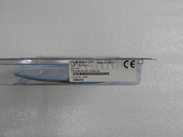
- Probe Type: 3300 XL NSv Probe (M10×1 thread, no armor)
- Unthreaded Length: 0 mm (Option 00)
- Overall Case Length: 250 mm (Option 25)
- Probe Cable Length: 0.5 meter (20 inches) integral (Option 05)
- Thread Size: M10 × 1 metric thread
- Connector: Miniature coaxial ClickLoc connector, standard cable (Option 02)
- Agency Approval: CN country-specific approvals (Option CN)
- Probe Tip Material: Polyphenylene sulfide (PPS)
- Probe Case Material: AISI 304 stainless steel (SST)
- Cable Specifications: 75Ω coaxial, fluoroethylene propylene (FEP) insulated
- Linear Range: 1.5 mm (60 mils) from 0.25 mm to 1.75 mm gap (approximately -1 to -13 VDC)
- Recommended Gap Setting: 1.0 mm (40 mils)
- Average Scale Factor (ASF) : 7.87 V/mm (200 mV/mil)
- Incremental Scale Factor (ISF) : ±12.5%/-20% including interchangeability error over linear range
- Deviation from Best Fit Straight Line (DSL) : Less than ±0.06 mm (±2.3 mils)
- Frequency Response: DC to 10 kHz (+0, -3 dB typical) with up to 305 meters field wiring
- Target Size (Flat Target) : Minimum 8.9 mm (0.35 in), recommended 13 mm (0.5 in)
- Shaft Diameter: Minimum 30 mm (1.2 in) for standard X-Y probe configuration
- Counterbore Minimum: 9.5 mm (0.375 in), recommended 13 mm (0.5 in)
- Operating Temperature (Probe) : -34°C to +177°C (-30°F to +351°F)
- Storage Temperature: -51°C to +177°C (-60°F to +351°F)
- Probe DC Resistance: 4.0 ± 0.5 ohms (0.5m length)
- Extension Cable DC Resistance: Center conductor 0.220Ω/m, shield 0.066Ω/m
- Extension Cable Capacitance: 69.9 pF/m (21.3 pF/ft) typical
- Field Wiring Maximum Length: 305 meters (1,000 feet) between Proximitor and monitor
- Environmental Rating: Sealed design with Viton O-ring for differential pressure applications
- Approvals: CN-specific hazardous area approvals (verify certificate details for project compliance)
Bently 330105-02-12-10-02-CN
The Real-World Problem It Solves
Rotating machinery in tight installations—centrifugal compressors, refrigeration compressors, and small-shaft equipment—often lack the space for standard 3300 XL 5mm or 8mm proximity probes. Counterbore restrictions, sideview limitations, and small target areas (shafts under 51mm or flat targets under 15mm) make conventional probes impossible to install. The 330905-00-25-02-CN NSv probe is specifically designed for these constrained environments, providing reliable non-contact measurement where standard probes cannot fit. Its compact form factor and enhanced side-view capabilities enable vibration and position monitoring on previously unmonitorable equipment.
Where you’ll typically find it:
- Centrifugal air compressors with tight clearance around bearing housings
- Refrigeration compressors with restricted counterbore access
- Process gas compressors on small shafts (under 51mm diameter)
- Axial position measurements on flat thrust collars smaller than 15mm
- Tachometer and Keyphasor installations where space is at a premium
Bottom line: This is the NSv proximity probe for space-constrained applications, delivering 200 mV/mil sensitivity in a package that fits where standard 3300 XL probes cannot.
Hardware Architecture & Under-the-Hood Logic
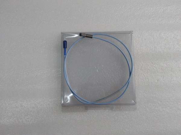
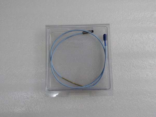
The 330905-00-25-02-CN is the probe component of the 3300 XL NSv Proximity Transducer System. It works in conjunction with a 3300 NSv extension cable and a 3300 XL NSv Proximitor Sensor. The probe contains a coil wound around a ferrite core, encapsulated in a PPS tip within a stainless steel housing. When powered by the Proximitor, the coil generates a high-frequency magnetic field that induces eddy currents in the conductive target surface. The strength of these eddy currents varies with gap distance, changing the coil impedance. The Proximitor detects this impedance change and converts it to a voltage proportional to gap distance. The probe’s 0.5-meter integral cable terminates in a ClickLoc connector for secure, tool-free connection to the extension cable.
-
Probe Construction: The probe consists of:
- PPS (Polyphenylene sulfide) tip material for chemical resistance
- AISI 304 stainless steel case body
- Internal coil wound on ferrite core
- Viton O-ring seal between tip and case for differential pressure applications
- Integral 0.5-meter 75Ω coaxial cable with FEP insulation
- Miniature coaxial ClickLoc connector
-
Eddy Current Generation: When the Proximitor excites the probe coil with high-frequency RF (typically 500 kHz to 1 MHz), the coil’s magnetic field penetrates the conductive target material. Circulating eddy currents are induced in the target surface according to Faraday’s law of induction.
-
Impedance Modulation: The eddy currents create their own opposing magnetic field (Lenz’s law), changing the effective impedance of the probe coil. This impedance change is a function of:
- Gap distance (primary measurement variable)
- Target material electrical conductivity
- Target material magnetic permeability
- Target geometry and surface condition
-
Signal Transmission: The probe’s integral 75Ω coaxial cable transmits the impedance-modulated signal to the Proximitor via the ClickLoc connector. The cable’s characteristic impedance (75Ω) matches the Proximitor input for optimal signal integrity.
-
ClickLoc Connection: The patented ClickLoc connector provides secure, finger-tight connection without tools. Gold-plated brass contacts ensure reliable electrical connection. The connector locks into place, preventing vibration-induced loosening—a common failure mode in high-vibration environments.
-
CableLoc Design: The probe incorporates the patented CableLoc design, providing 220N (50 lbf) of pull strength between the cable and probe body. This prevents cable strain from damaging the internal coil connection, a critical reliability feature in high-vibration applications.
-
TipLoc Bonding: The probe tip is bonded to the case body using the patented TipLoc molding method, creating a robust mechanical and environmental seal. This prevents tip separation under thermal cycling and vibration.
-
O-Ring Seal: A Viton O-ring between the probe tip and case allows the probe to seal differential pressure. This enables installation in pressurized machine housings where oil or gas leakage through the probe penetration must be prevented.
-
System Electrical Length Matching: The probe, extension cable, and Proximitor must have consistent electrical lengths. The 0.5-meter probe requires a specific extension cable length to match the Proximitor’s system length (typically 5.0 or 7.0 meters total). Mismatched electrical lengths cause calibration errors.
-
Target Material Considerations: The NSv system is calibrated for AISI 4140 steel targets. For non-ferrous materials (aluminum, brass, stainless steel), the scale factor changes. Material correction factors must be applied in the monitor configuration or by ordering a probe calibrated for the specific target material.
Bently 330105-02-12-10-02-CN
Field Service Pitfalls: What Rookies Get Wrong
Mismatching Electrical Length in NSv SystemTechs replace a failed 0.5-meter NSv probe but keep the existing 5-meter extension cable with a 5.0-meter Proximitor. The total system length becomes 10.5 meters instead of the specified 5.0 meters. The Proximitor’s internal calibration is mismatched, causing sensitivity errors of 15-20% and incorrect vibration readings.
- Field Rule: The electrical length of the probe plus extension cable must exactly match the Proximitor’s rated system length. For a 5.0-meter Proximitor, if using a 0.5-meter probe, the extension cable must be 4.5 meters. Verify system length by checking the Proximitor label (e.g., “5.0m System”) and ensuring probe + extension cable equals this value.
Installing NSv Probe in Exceedingly Small CounterboreNovices install NSv probes in counterbores smaller than the recommended 13mm (0.5 in). The 9.5mm minimum counterbore works but causes the probe’s magnetic field to interact with the counterbore walls, changing the scale factor at far gaps. Vibration amplitude errors of 10-15% occur, and the linear range shrinks from 1.5mm to approximately 1.0mm.
- Quick Fix: Maintain minimum 13mm counterbore diameter whenever possible. If a smaller counterbore is unavoidable, reduce the working gap (set gap closer to 0.75mm instead of 1.0mm) to maintain scale factor accuracy over the reduced linear range. Re-verify calibration with a known target displacement after installation.
Ignoring Target Diameter Limits on Small ShaftsYoung engineers install NSv probes on shafts smaller than 30mm (1.2 in) diameter for radial vibration measurements. The small target area cannot support the probe’s magnetic field properly, causing the Average Scale Factor (ASF) to change by more than 10%. At 50 mils vibration, the monitor shows 45 mils or 55 mils, leading to missed or false alarms.
- Field Rule: Minimum shaft diameter for NSv radial vibration probes is 30mm (1.2 in). For shafts smaller than this, consider using standard 8mm probes if space permits, or apply a custom scale factor correction based on actual diameter. If small shaft diameter is unavoidable, measure and verify the scale factor using a calibrator or known displacement source.
Over-Tightening M10×1 Thread During InstallationTechs torque the M10×1 probe thread to specifications for standard steel fittings (often 15-20 ft-lbs). The stainless steel probe case galls in the aluminum or cast iron housing, seizing the thread. During maintenance, the probe cannot be removed without destroying the mounting boss or cutting the probe.
- Quick Fix: Apply anti-seize compound to the M10×1 threads before installation. Torque to Bently Nevada specifications—typically finger-tight plus 1/8 turn with pliers for ClickLoc connections, or 5-7 ft-lbs for permanent installations. Never use a torque wrench set to standard bolt specifications without verifying the manufacturer’s recommendation.
Failing to Use Connector Protectors in Wet EnvironmentsRookies connect the probe-to-extension cable ClickLoc connector without installing a connector protector. In oil-lubricated compressors, oil migrates into the connector, causing signal degradation and intermittent connections. The monitor shows erratic vibration readings that correlate with oil temperature changes.
- Field Rule: Always install connector protectors on both probe-to-extension cable and extension cable-to-Proximitor connections in any environment where oil, moisture, or contaminants are present. The protectors seal the ClickLoc connectors, preventing liquid ingress. Alternatively, use silicone tape (provided with extension cables), but tape is not recommended for turbine oil applications—oil degrades the tape over time.
Incorrect Gap Setting on Small Flat TargetsTechs set the NSv probe gap to 1.0 mm (40 mils) on a flat thrust collar smaller than the recommended 13mm diameter. The small target causes edge effects at the probe periphery, making the gap voltage nonlinear. The axial position reading drifts by 2-3 mils as the shaft rotates, causing false thrust position warnings.
- Field Rule: For flat targets smaller than 15mm, reduce the gap to 0.75mm (30 mils) or less to minimize edge effects. Verify axial position stability by rotating the shaft and observing gap voltage—the reading should be stable within ±0.5V DC. If instability persists, consider installing a larger target ring or using a different measurement method.
Mixing FluidLoc and Standard Cable OptionsMaintenance personnel replace a standard cable NSv probe with a FluidLoc cable variant without notifying the monitoring team. FluidLoc cable has different capacitance and impedance characteristics, causing subtle calibration shifts. Over 6 months of operation, vibration trends show unexplained 5% amplitude drift.
- Field Rule: Never mix cable types within a transducer system. If the original installation used standard cable (Option 02), the replacement must also use standard cable. FluidLoc cable (Option 12) is designed for applications where oil leakage through the cable must be prevented—it has different electrical properties. Always match the cable-type option when ordering replacement probes.
Commercial Availability & Pricing Note
Please note: The listed price is for reference only and is not binding. Final pricing and terms are subject to negotiation based on current market conditions and availability.


