
Description
Hard-Numbers: Technical Specifications
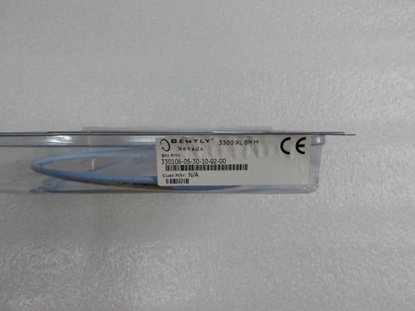
- Probe Tip Diameter: 8 mm
- Probe Length: 0.5 to 20 meters (configurable via interconnect cable length)
- Thread Size: 1/4-28 UNF (standard), M8×1, 3/8-24 UNF (optional variants)
- Probe Housing Material: Stainless steel (316SS standard)
- Measurement Range: 2 mm (80 mils) linear range from -0.25 to +1.75 mm gap
- Sensitivity: 200 mV/mil (7.87 mV/µm) at 1 kHz
- Frequency Response: 0 Hz (DC) to 8 kHz (-3 dB)
- Accuracy: ±1% of full scale (linearity)
- Temperature Range:
- Operating: -51°C to +177°C (-60°F to +350°F)
- Storage: -51°C to +177°C
- Terminal Resistance:
- Probe: Typically 7-12 ohms (depends on cable length)
- Proximitor: 12.5k ohms (across probe terminals)
- Isolation: 500V RMS galvanic isolation
- Probe Cable:
- Conductor: Tinned copper, 28 AWG twisted pair
- Insulation: PTFE (Teflon) for high-temperature applications
- Shield: Overall braid + foil (double shielding)
- Jacket: High-temperature fluoropolymer
- Connector Type:
- Probe End: Integral micro connector (hermaphroditic)
- Proximitor End: DIN 43650 connector
- Interconnect Cable Length: 3, 5, 7.5, 10, 15 meters standard (field-configurable)
- Power Supply: -17.5 to -26 V DC (from Proximitor)
- Environmental Rating: IP67 (probe housing with proper conduit)
- Approvals: CSA, CENELEC (for hazardous locations)
Bently 330105-02-12-10-02-CN
The Real-World Problem It Solves
Rotating machinery failures—bearing wear, shaft misalignment, seal leaks, and coupling problems—manifest as abnormal vibration patterns and axial shaft movement long before catastrophic failure occurs. The 330105-02-12-10-02-CN provides reliable, non-contact measurement of shaft radial vibration, axial position, and speed using eddy current technology. The 8mm system balances measurement range and sensitivity for general-purpose machinery monitoring applications, serving as the workhorse transducer in most Bently Nevada protection systems.
Where you’ll typically find it:
- Steam and gas turbine radial vibration and thrust position monitoring
- Centrifugal compressor shaft vibration and axial position
- Motor and pump bearing vibration and position measurement
- Gearbox shaft vibration monitoring
- Small to medium-sized rotating machinery in API 670 protection systems
Bottom line: This is the standard 8mm proximity transducer system for Bently Nevada 3500 monitoring systems, converting physical shaft motion into analog voltage signals for machinery protection and condition monitoring.
Hardware Architecture & Under-the-Hood Logic
The 330105-02-12-10-02-CN is a three-component eddy current transducer system consisting of a probe (sensor tip), interconnect cable, and proximitor (signal conditioner). The probe generates an alternating magnetic field that induces eddy currents in the conductive target surface. The strength of these eddy currents changes as the gap between probe tip and target surface varies, causing a corresponding change in the probe coil impedance. The proximitor detects this impedance change and converts it to a DC voltage proportional to the gap distance.
-
Probe Construction: The probe contains a coil wound around a ferrite core, encapsulated in a stainless steel housing. When powered by the proximitor, the coil generates a high-frequency RF magnetic field (typically 500 kHz to 1 MHz depending on system design).
-
Eddy Current Generation: The probe’s magnetic field penetrates the conductive target material (typically steel shaft or thrust collar). According to Faraday’s law of induction, circulating eddy currents are induced in the target surface.
-
Impedance Change: These eddy currents create their own magnetic field that opposes the probe’s field (Lenz’s law), changing the effective impedance of the probe coil. The impedance change is a function of:
- Gap distance (primary variable)
- Target material electrical conductivity
- Target material magnetic permeability
-
Proximitor Signal Conditioning: The proximitor contains an RF oscillator that drives the probe coil and a demodulator that detects impedance changes. Key internal components:
- Oscillator: Generates high-frequency excitation signal (typically 500 kHz – 1 MHz)
- Demodulator: Converts impedance variations to DC voltage output
- Amplifier: Scales the signal to the standard sensitivity (200 mV/mil)
- Output Circuit: Provides DC gap voltage superimposed with AC vibration signal
- Terminal: -24V DC power input and signal output
-
Signal Composition: The proximitor output is a composite signal containing:
- DC Offset (Gap Voltage) : Proportional to the average gap distance (e.g., -10V DC at mid-gap)
- AC Component: Superimposed vibration signal (e.g., ±500 mV peak vibration)
- Total Output = DC gap voltage + AC vibration signal
-
Linearization: The relationship between gap distance and output voltage is non-linear (following a curve). The proximitor applies a linearization algorithm to provide a linear output over the specified measurement range (typically -0.25 to +1.75 mm gap for 8mm systems). Linear range is approximately 20-25% of probe diameter.
-
Target Material Compensation: The proximitor can be calibrated for different target materials (typically AISI 4140 steel standard). For non-ferrous materials (e.g., aluminum, brass), a material correction factor is applied in configuration to compensate for different eddy current response.
-
Temperature Compensation: The probe coil and proximitor circuitry exhibit temperature drift. The 3300 XL design includes temperature compensation circuitry that minimizes sensitivity drift to less than ±0.5% over the operating temperature range.
-
Electrical Isolation: The transducer system provides galvanic isolation (typically 500V RMS) between the probe circuitry and the proximitor output, protecting monitoring equipment from ground loops and common-mode voltages.
Bently 330105-02-12-10-02-CN
Field Service Pitfalls: What Rookies Get Wrong
Incorrect Target Material SelectionTechs install an 8mm probe calibrated for AISI 4140 steel target material on an aluminum turbine shaft without applying the material correction factor. The eddy current response differs for aluminum vs. steel, causing sensitivity errors of 30-50% and false vibration readings. The monitor shows 6 mils vibration when actual shaft vibration is only 4 mils.
- Field Rule: Always match the transducer calibration to the target material. Bently Nevada probes are typically calibrated for AISI 4140 steel. For aluminum, brass, or stainless steel shafts, apply the material correction factor in the monitor configuration or use probes specifically calibrated for those materials. The factor ranges from 0.7 to 1.3 depending on material conductivity and permeability.
Probe Installed in Mechanical Runout AreaNovices mount probes at locations with obvious mechanical runout—scratches, dents, or surface irregularities on the shaft. The probe measures surface irregularities as vibration, causing false high vibration readings even on a perfectly balanced shaft. At 3600 RPM, a 0.5 mil scratch appears as 0.5 mil vibration at 1X RPM.
- Quick Fix: Choose probe locations on smooth, machined shaft surfaces away from keyways, coupling bolts, and surface defects. If unavoidable, perform slow roll compensation (measure and subtract mechanical runout) during commissioning. Use a dial indicator to verify shaft surface runout is less than 0.2 mils before installing proximity probes.
Wrong Gap Setting Causing Non-Linear OperationTechs set the probe gap too close to the shaft (e.g., 10 mils gap on an 80 mil linear range probe). During normal operation, the shaft moves ±30 mils, causing the gap to drop to -20 mils (below linear range) and exceed the linear range upper bound. The proximitor output becomes non-linear, and the monitor shows distorted vibration waveforms and incorrect amplitude readings.
- Field Rule: Set initial gap to the linear range midpoint (typically 40-50 mils from target surface for 8mm probes). Verify gap voltage is within the specified linear range (typically -4V to -16V DC for 8mm systems) in the monitor. Allow adequate margin for expected shaft motion and thermal expansion. Never operate near the linear range limits.
Using Standard Cable in High-Temperature ApplicationsRookies install standard 330105 probes on gas turbine exhaust bearings where ambient temperature exceeds 150°C. The standard cable jacket and insulation degrade rapidly, causing cable failure within weeks. The probe signal becomes intermittent or drops to zero, triggering false alarms.
- Field Rule: For high-temperature applications (above 125°C ambient), use high-temperature probe variants with PTFE (Teflon) insulation and fluoropolymer cable jackets. The 330105-02-12-10-02-CN with “-CN” suffix typically indicates China market variant—verify temperature rating matches application. If cable routing through hot zones is unavoidable, install thermal barriers or use armored high-temperature cable.
Improper Cable Routing Through EMI SourcesTechs route probe cables alongside VFD output cables or high-current motor leads. Electromagnetic interference from VFD switching (20-60 kHz carrier frequency) couples into the sensitive millivolt probe signals, causing apparent vibration noise of 2-5 mils on the monitor. The noise appears as broadband high-frequency spikes that correlate with VFD operation.
- Field Rule: Route transducer cables in grounded metal conduit, separated from power cables by at least 12 inches (30 cm). Use double-shielded cable (foil + braid) for maximum EMI rejection. Ground the shield at the proximitor end only (single-point grounding) to avoid ground loops. Verify signal quality with an oscilloscope during commissioning—look for VFD-related noise riding on the vibration signal.
Ignoring Perpendicularity During Probe MountingYoung engineers mount probes at 10-15 degrees off-perpendicular to the shaft surface without compensating in configuration. The effective gap increases by the cosine of the angle (cos 15° = 0.966), causing 3.4% sensitivity reduction and measurement error. At 10 mils vibration, the monitor shows only 9.66 mils—a 0.34 mil error that compounds over time.
- Field Rule: Mount probes as perpendicular to the shaft surface as possible (within 3 degrees). Verify perpendicularity by rotating the shaft and observing gap voltage—the reading should be stable within ±0.5V DC. If angle cannot be avoided, apply an angle correction factor in monitor configuration or use a mechanical mounting bracket that ensures perpendicular alignment.
Incorrect Total Cable Length ConfigurationTechs install a 5-meter probe with 10-meter interconnect cable (15 meters total) but configure the monitor for 5-meter cable length. The additional cable capacitance (typically 50 pF/m) causes phase shift and signal attenuation. Vibration amplitude errors of 5-10% occur at high frequencies (above 1 kHz), and phase shift can affect timing measurements.
- Field Rule: Configure the monitor for the total cable length from probe tip to proximitor input. For the 330105 system, total cable length is typically 3-20 meters. If using a 5-meter probe with 10-meter extension, configure for 15 meters total. The monitor applies cable length compensation to correct for capacitive effects. Verify system response by injecting a known calibration signal at different frequencies.
Commercial Availability & Pricing Note
Please note: The listed price is for reference only and is not binding. Final pricing and terms are subject to negotiation based on current market conditions and availability.


