
Description
Hard-Numbers: Technical Specifications
- Channels: 16 independent temperature input channels
- Input Types Supported: RTD (Pt100, Pt1000, Ni100, Cu10, etc.), Thermocouple (J, K, T, E, N, B, R, S, C), mV, 4-20 mA
- RTD Configurations: 2-wire, 3-wire, 4-wire (auto-detection)
- Thermocouple Reference: Automatic cold junction compensation (CJC)
- Measurement Range:
- RTD: -200°C to +850°C (-328°F to +1562°F)
- Thermocouple: -270°C to +2315°C (-454°F to +4199°F) dependent on type
- Accuracy:
- RTD: ±0.1°C at 0°C (Pt100 3-wire)
- Thermocouple: ±1.1°C or ±0.75% (Type K, typical)
- Resolution: 0.1°C (0.18°F)
- Update Rate: 100 ms per channel
- Alarm Outputs: Programmable Alert and Danger setpoints per channel with configurable time delays (0.1-60 seconds)
- Relay Outputs: Integrated SPDT relay contacts (channels 1-4 shared, or via 3500/32/33 modules)
- Communication: Modbus RTU over RS-485, Ethernet/IP via 3500/92 gateway
- Protocol Support: Modbus RTU, Modbus TCP, Ethernet/IP (via gateway)
- Port Count: 1 RS-485 terminal block, backplane communication
- Baud Rate: 1200, 2400, 4800, 9600, 19200 bps (configurable)
- Isolation Rating: 500V RMS galvanic isolation between inputs and backplane
- Power Draw: 10W typical (from 3500 rack power supply)
- Operating Temperature: -30°C to +65°C (-22°F to +149°F)
- Storage Temperature: -40°C to +85°C (-40°F to +185°F)
- Humidity: 0% to 95% non-condensing RH
- Dimensions: 241.3mm (H) × 24.4mm (W) × 241.8mm (D) (9.50″ × 0.96″ × 9.52″)
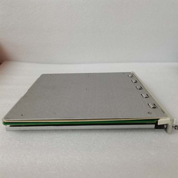
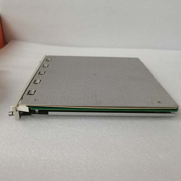
- Slot Requirements: Standard 3500 rack slot (single-width module)
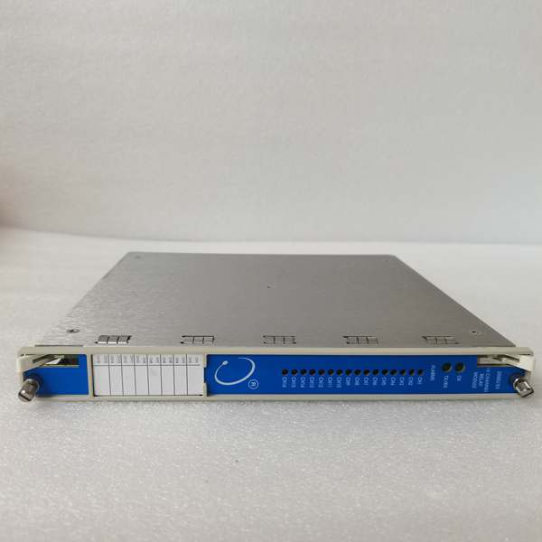
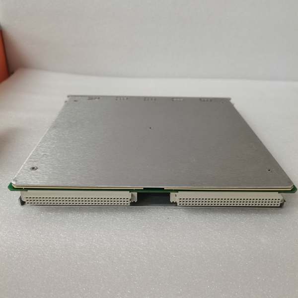
Bently 149986-01
The Real-World Problem It Solves
Rotating equipment failures often manifest first as abnormal temperature rise in bearings, bushings, or motor windings—thermal symptoms precede mechanical failure by hours or days. The 3300/65 provides universal temperature monitoring across 16 channels with mixed sensor types (RTDs and thermocouples on the same module), detecting thermal anomalies before they escalate to catastrophic damage. This eliminates the need for separate RTD and thermocouple monitor modules, reducing rack space and hardware cost.
Where you’ll typically find it:
- Steam turbine bearing temperature monitoring (journal bearings, thrust bearings)
- Motor bearing and winding temperature protection in pumps and compressors
- Process temperature monitoring in gas turbines and reciprocating compressors
- Critical machinery with mixed RTD/thermocouple sensor requirements
Bottom line: This is the universal temperature monitor for 3500 systems, supporting any combination of RTDs and thermocouples on a single 16-channel module with programmable alarm protection.
Hardware Architecture & Under-the-Hood Logic
The 3300/65 is a 16-channel temperature monitor module that plugs into the 3500 rack backplane. It accepts analog signals from RTDs (resistance-based) and thermocouples (mV-based), digitizes them using high-resolution ADCs, applies linearization and cold junction compensation algorithms, converts measurements to engineering units, and outputs alarm status to relay modules. The module operates as an intelligent node on the backplane with its own microprocessor for signal processing, alarm logic, and communication.
-
Input Signal Reception: Each of the 16 channels accepts various sensor types:
- RTD inputs: 2-wire, 3-wire, or 4-wire configurations (auto-detected)
- Thermocouple inputs: Type J, K, T, E, N, B, R, S, C
- Analog inputs: mV or 4-20 mA signals
-
Signal Conditioning:
- RTD channels use constant current excitation (typically 1 mA) and measure voltage drop across the sensor
- Thermocouple channels measure the small mV signal generated by the Seebeck effect
- 4-20 mA channels use a precision shunt resistor (250 ohms typical)
-
Analog-to-Digital Conversion: All conditioned signals are digitized by a 24-bit ADC at a sampling rate of 100 Hz per channel. High resolution ensures accurate temperature measurement across the full range.
-
Linearization and Compensation:
- RTD measurements apply Callendar-Van Dusen equation for Pt sensors
- Thermocouple measurements apply ITS-90 thermocouple reference tables with automatic cold junction compensation (CJC) using onboard temperature sensor
- Each channel stores calibration coefficients in non-volatile memory
-
Temperature Calculation: Digitized values are converted to engineering units (°C or °F) based on sensor type and calibration data. The module calculates:
- Instantaneous temperature value
- Rate of change (dT/dt) if enabled
- Average value over configurable time window
-
Alarm Comparison: Calculated temperature values are continuously compared against user-programmed Alert and Danger setpoints (configured via 3500 Configuration Software). Alarm scenarios include:
- Temperature exceeding Alert setpoint
- Temperature exceeding Danger setpoint
- Rate of change exceeding configured threshold
- Sensor fault (open circuit, short circuit)
-
Alarm Output: Alarm status signals are transmitted to the 3500/32, 3500/33, or 3500/34 Relay Modules via the backplane. These modules drive external relay contacts for annunciation and machine trip functions.
-
Communication: Processed data (temperature values, alarm status, diagnostic information) is transmitted via Modbus RTU (RS-485) or through the 3500/92 gateway for Ethernet/IP communication to external systems (DCS, PLC, historians). The module supports both polling and event-driven data transmission.
-
Self-Diagnostics: The module continuously monitors its own health and the integrity of connected sensors. Faults detected include:
- RTD open circuit or short circuit
- Thermocouple open circuit, reverse polarity, or out-of-range
- Over/under range detection
- Internal module hardware faults
- Communication failures
-
Configuration and Calibration: Channel configuration is stored in non-volatile memory and can be programmed via 3500 Configuration Software. The module supports:
- Per-channel sensor type selection
- Sensor curve selection (Pt100, Pt1000, Type K, etc.)
- Alarm setpoint programming
- Time delay configuration
- Input filtering (digital filtering to suppress noise)
Bently 149986-01
Field Service Pitfalls: What Rookies Get Wrong
Using 2-Wire RTDs in Long Cable Runs Without Lead Resistance CompensationTechs install 2-wire RTDs on 300-foot cable runs to distant motor bearings. The lead resistance (approximately 0.5 ohms per 100 feet for 18 AWG) adds 1.5 ohms total resistance, causing a temperature reading error of +3.8°C for Pt100 sensors. The monitor shows 85°C when actual bearing temperature is 81.2°C, causing false Danger alarms during normal operation.
- Field Rule: For cable runs over 50 feet, always use 3-wire or 4-wire RTD configurations. The module automatically compensates for lead resistance in 3-wire and 4-wire modes. If 2-wire must be used, manually enter lead resistance value in configuration or install the module closer to the sensor.
Mixing Thermocouple Wire Types in the Same CircuitNovices splice Type K thermocouple extension wire into a Type J thermocouple circuit halfway to the monitor. The dissimilar metals create additional thermocouple junctions, introducing measurement errors of 20-30°C. The monitor shows erratic temperature readings that fluctuate with ambient temperature at the splice point.
- Quick Fix: Never splice different thermocouple wire types together. Use the same thermocouple type extension wire as the sensor (Type J extension wire for Type J sensors). Color codes vary by standard—verify wire type with a thermocouple calibrator before installation.
Ignoring Ground Loops When Grounding Thermocouple SheathsYoung engineers ground the metal sheath of thermocouple probes at both the sensor mounting point (compressor casing) and the monitor chassis. This creates a ground loop that induces millivolt-level noise on the thermocouple signal, causing temperature readings to drift by 5-10°C when VFDs or large motors start nearby.
- Field Rule: Ground thermocouple sheaths at one location only—typically at the sensor mounting point if it provides a safety ground, or at the monitor end if the sensor is isolated. Verify ground potential difference between sensor and monitor chassis is less than 1V AC. Use isolated thermocouple inputs if ground loops cannot be avoided.
Incorrect RTD Excitation Current SettingsTechs configure the module for 1 mA excitation current on 1000-ohm Pt1000 RTDs used for motor winding temperature. The RTD self-heats due to excessive power dissipation (P = I²R = 1² × 1000 = 1000 mW = 1W), causing the temperature reading to drift upward by 5-8°C even when the motor is 终止ped and at ambient temperature.
- Field Rule: Match excitation current to RTD resistance. Use 0.1 mA or 0.25 mA excitation for 1000-ohm RTDs (Pt1000), and 1 mA for 100-ohm RTDs (Pt100). The 3300/65 typically auto-configures excitation based on sensor type, but verify this in the channel configuration screen.
Forgetting Cold Junction Compensation (CJC) Reference TemperatureRookies install thermocouple inputs without verifying CJC is enabled or configured. The module assumes 0°C reference temperature, but the actual terminal block temperature is 35°C (typical cabinet temperature). This introduces a constant offset error equal to the terminal block temperature (e.g., Type K generates 1.4 mV at 35°C = +35°C error).
- Quick Fix: Always ensure CJC is enabled for thermocouple inputs in the module configuration. The 3300/65 has onboard CJC sensors that automatically compensate for terminal block temperature. Verify CJC status by monitoring the diagnostic parameter “CJC Temperature” in the software—it should read close to ambient cabinet temperature.
Improper Shield Termination Causing NoiseTechs ground both ends of thermocouple extension wire shields—at the sensor thermowell and at the monitor terminal block. Ground loops induced by nearby VFDs corrupt the millivolt thermocouple signal, causing temperature readings to jump randomly by 2-5°C.
- Field Rule: Ground thermocouple cable shields at the monitor end only. Leave the sensor end shield floating or connected through a capacitor if EMI suppression is needed. Use twisted-pair thermocouple wire with overall foil or braid shield for maximum noise rejection.
Overlooking Input Filter Settings for Fast Temperature ChangesYoung engineers leave input filters at default settings (heavy filtering) when monitoring turbine steam temperature that changes rapidly during startup transients. The heavily filtered temperature reading lags actual temperature by 10-15 seconds, causing the monitor to miss rapid temperature excursions during load changes.
- Field Rule: Adjust input filter time constant based on process dynamics. Use faster filter settings (0.5-1 second) for applications with rapid temperature changes (turbine steam temperature, process vessels). Use slower filters (5-10 seconds) for stable thermal processes (bearing temperatures) to suppress noise.
Commercial Availability & Pricing Note
Please note: The listed price is for reference only and is not binding. Final pricing and terms are subject to negotiation based on current market conditions and availability.


