

Description
Hard-Numbers: Technical Specifications
- Channels: 4 independent channels
- Input Signal: Proximity transducer (gap voltage -20V to +2V DC) from 3300/3300 XL/7200 series transducers
- Measurement Range: ±25 mm (±1 inch) full scale (configurable to match compressor stroke)
- Frequency Response: DC to 100 Hz (-3 dB) optimized for reciprocating motion
- Accuracy: ±1% of full scale (position)
- Alarm Outputs: Programmable Alert and Danger setpoints per channel with configurable time delays
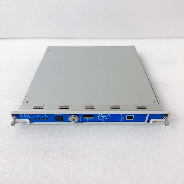
- Communication: Ethernet (10/100Base-T) and Modbus RTU (RS-485) built-in
- Protocol Support: TCP/IP, UDP/IP, Modbus RTU, Modbus TCP (via 3500/92 gateway)
- Port Count: 1 RJ-45 Ethernet port, 1 RS-485 terminal block (2-wire)
- Baud Rate: 1200, 2400, 4800, 9600, 19200 bps (Modbus RTU configurable)
- Operating Temperature: -30°C to +65°C (-22°F to +149°F)
- Storage Temperature: -40°C to +85°C (-40°F to +185°F)
- Humidity: 0% to 95% non-condensing RH
- Isolation Rating: 1500V RMS galvanic isolation between inputs and backplane
- Power Draw: 7.7W typical (from 3500 rack power supply)
- Buffered Outputs: 4 buffered transducer outputs (rear panel BNC connectors)
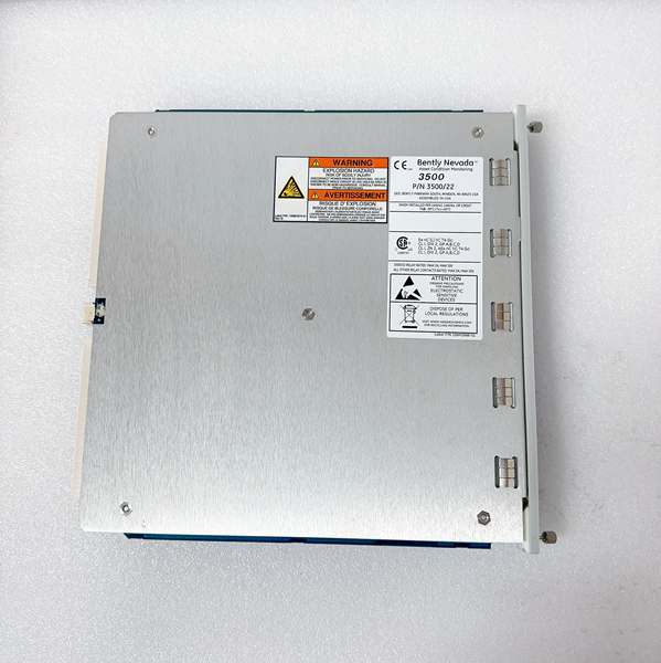
- Dimensions: 241.3mm (H) × 24.4mm (W) × 241.8mm (D) (9.50″ × 0.96″ × 9.52″)
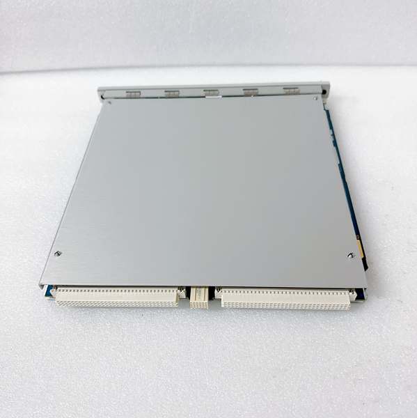
- Slot Requirements: Standard 3500 rack slot (single-width module)
BENTLY 288055-01
The Real-World Problem It Solves
Reciprocating compressors can suffer catastrophic failures when rod position sensors fail or mechanical abnormalities go undetected—leading to rod drop, cylinder damage, or catastrophic compressor failure. The 288055-01 provides continuous monitoring of rod position, crosshead movement, and cylinder unloader status, comparing measured values against programmable setpoints to trigger alarms before mechanical damage occurs. This module replaces outdated mechanical limit switches with continuous, high-precision electronic measurement and programmable alarms.
Where you’ll typically find it:
- Large reciprocating compressors in gas processing plants (API 618 compressors)
- Hydrogen compressors in refinery hydrogen units monitoring rod position to prevent cylinder wall scoring
- Natural gas pipeline compressor stations with critical rod load limits
- Recip compressors in petrochemical ethylene plants tracking crosshead drift during startup and load changes
Bottom line: This is the dedicated reciprocating rod position monitor for 3500 systems, turning proximity transducer signals into actionable protection for reciprocating machinery.
Hardware Architecture & Under-the-Hood Logic
The 288055-01 is a 4-channel monitor module that plugs into the 3500 rack backplane. It receives analog gap voltage signals from proximity transducers (installed on compressor crossheads or cylinder heads), digitizes them using 16-bit ADCs, applies user-configured signal processing algorithms for position calculation, and outputs alarm status to rack’s relay modules. Communication with external systems occurs via Ethernet or Modbus RTU interfaces. The module operates as an intelligent, isolated node on the 3500 backplane with its own microprocessor for signal processing and alarm logic.
-
Signal Reception: Each channel receives a gap voltage signal (-20V to +2V DC) from a proximity transducer (3300/3300 XL/7200 series) mounted to monitor compressor rod or crosshead position. The signal represents the physical gap between the probe tip and the target surface (typically a machined surface on the crosshead or rod).
-
Analog-to-Digital Conversion: The incoming analog gap voltage is digitized by a 16-bit ADC at a sampling rate of 1 kHz. The high resolution ensures accurate representation of the slow reciprocating motion (typically 300-1200 RPM).
-
Position Calculation: Digitized signals are processed to calculate position parameters:
- Rod Position: DC-coupled signal represents absolute rod position relative to probe
- Top Dead Center (TDC)/Bottom Dead Center (BDC) : Peak position detection over each reciprocating cycle
- Rod Drop: Sudden change in DC position indicating mechanical failure (broken bolt, loose connection)
- Stroke Verification: Confirms measured stroke matches configured stroke length (±10% tolerance)
-
Alarm Comparison: Calculated position values are continuously compared against user-programmed Alert and Danger setpoints (configured via 3500 Configuration Software). Common alarm scenarios include:
- Rod position exceeding mechanical limits
- Abnormal stroke detection (short stroke indicating valve issues)
- Rod drop detection (sudden position change indicating mechanical failure)
- Cylinder unloader position verification
-
Alarm Output: Alarm status signals are transmitted to the 3500/32 or 3500/33 Relay Modules via the backplane. These modules drive external relay contacts for annunciation and compressor trip functions.
-
Communication: Processed data (rod position, stroke length, alarm status, diagnostic information) is transmitted via Ethernet (TCP/IP) or Modbus RTU (RS-485) to external systems (DCS, PLC, historians). The module supports both polling and event-driven data transmission.
-
Buffered Output: Each channel provides a buffered reproduction of the transducer signal on the rear panel (BNC connectors) for connection to external data acquisition systems or portable analyzers without disrupting the primary signal path.
-
Self-Diagnostics: The module continuously monitors its own health and the integrity of connected transducers. Faults detected include:
- Transducer open circuit
- Transducer short circuit
- Out-of-range gap voltage
- Stroke verification failure
- Internal module hardware faults
- Communication failures
BENTLY 288055-01
Field Service Pitfalls: What Rookies Get Wrong
Incorrect Stroke Configuration Leading to False AlarmsTechs configure the stroke length based on compressor nameplate data without verifying actual mechanical stroke. If the configured stroke is 6 inches but the actual mechanical stroke is 5.5 inches, the module detects a “short stroke” fault on every cycle because the measured position never reaches the expected TDC/BDC limits. The compressor runs fine, but the monitor triggers continuous nuisance alarms.
- Field Rule: Always verify actual mechanical stroke using a dial indicator or by manually jogging the compressor and observing position readings. Configure the module’s stroke length to match measured mechanical stroke within ±5%. Don’t trust nameplate data alone—manufacturing tolerances exist.
Mounting Probes on Vibrating Surfaces Instead of CrossheadNovices mount rod position probes on the compressor crankcase or cylinder support structure instead of the crosshead itself. The probe measures structural vibration rather than actual rod position, causing the position reading to drift randomly as the compressor operates. At 600 RPM, the reading fluctuates by ±10 mils when it should be stable at 50 mils.
- Quick Fix: Mount proximity probes directly on the crosshead or rod clamp mechanism—not on stationary supports. The target surface must move with the rod, not vibrate with the machine. Verify probe mounting by watching the position reading while manually moving the rod through its full stroke.
Ignoring Rod Drop Detection SettingsYoung engineers configure position alarms but leave the rod drop detection feature disabled. When a crosshead bolt fails and the rod drops 0.5 inches, the position monitor sees the sudden change but doesn’t trigger an alarm because the rod drop function wasn’t enabled. The compressor continues running for 30 seconds until catastrophic mechanical damage occurs.
- Field Rule: Always enable rod drop detection for reciprocating compressor applications. Configure the rod drop threshold to 10-20% of stroke length—sudden position changes exceeding this limit indicate mechanical failure and should trigger an immediate Danger alarm. Test the function by simulating a rapid position change during commissioning.
Wrong Probe Gap Setting for Temperature CompensationTechs set the rod position probe gap at mid-stroke (e.g., 50 mils) without considering thermal expansion. As the compressor heats up from ambient to operating temperature (e.g., 80°C temperature rise), the crosshead expands and the effective gap changes by ±5 mils. The position reading shifts, and at full stroke, the probe may saturate, missing actual TDC/BDC detection.
- Field Rule: Set probe gap accounting for expected thermal expansion. For typical crosshead materials (cast iron or steel), allow 10-15 mils additional gap beyond mid-stroke to accommodate thermal growth. Calculate thermal expansion: ΔL = L × α × ΔT, where α is the coefficient of thermal expansion for the crosshead material.
Using Standard Vibration Probes Instead of Position ProbesRookies install standard 8mm vibration probes (3300 XL 8mm) instead of extended range position probes (25mm range). The standard probe’s linear range is only 2 mm (80 mils), but reciprocating compressor strokes often exceed 4-6 inches (100-150 mils). The probe saturates at both TDC and BDC, providing no useful position data and triggering constant “out of range” faults.
- Field Rule: Use Extended Range Proximitor probes (e.g., 3300 XL 25mm Extended Range) with compatible range for the compressor stroke. For a 6-inch stroke, use a probe with at least 8-inch linear range to avoid saturation at stroke extremes. Never exceed 70% of the probe’s linear range at full stroke.
Improper Shield Grounding Causing Position DriftTechs ground the shield of rod position transducer cables at both the transducer end and the monitor end. This creates a ground loop that introduces DC offset into the position signal. The monitor shows a false position shift of 5-10 mils, causing the rod position to appear off-center even when mechanically centered.
- Quick Fix: Ground the shield cables at the monitor end only. Leave the transducer end shield floating to avoid ground loops. Verify ground potential difference between the crosshead (where the transducer mounts) and the monitor chassis—must be less than 1V AC to prevent offset errors.
Commercial Availability & Pricing Note
Please note: The listed price is for reference only and is not binding. Final pricing and terms are subject to negotiation based on current market conditions and availability.


