
Description
Hard-Numbers: Technical Specifications
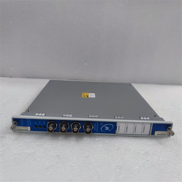
- Channels: 4 independent channels (paired configuration: Ch1-2 and Ch3-4)
- Input Signal: Proximitor signal (gap voltage -20V to +2V DC) from 3300/3300 XL/7200 series transducers
- Supported Proximitor Types: 3300 (5mm, 8mm, 11mm, 14mm), 3300 XL (8mm, 11mm, 14mm), 7200 series
- Measurement Capabilities:
- Radial Vibration: 0-2 mm pk-pk (10-0-10 mils typical)
- Axial Position (Thrust): ±2 mm (±80 mils)
- Eccentricity: ±2 mm
- Differential Expansion: ±2 mm
- Frequency Response: DC to 10 kHz (±1 dB)
- Accuracy: ±1% of full scale (vibration), ±0.1% of full scale (position)
- Alarm Outputs: Programmable Alert and Danger setpoints per channel
- Communication: Ethernet (10/100Base-T) and Modbus RTU (RS-485) built-in
- Power Consumption: 7.7W typical (from 3500 rack power supply)
- Operating Temperature: -30°C to +65°C (-22°F to +149°F)
- Storage Temperature: -40°C to +85°C (-40°F to +185°F)
- Humidity: 0% to 95% non-condensing RH
- Buffered Outputs: 4 buffered transducer outputs (rear panel)
- Isolation: 1500V RMS galvanic isolation between inputs and backplane
- Dimensions: 241.3mm (H) × 24.4mm (W) × 241.8mm (D) (9.50″ × 0.96″ × 9.52″)
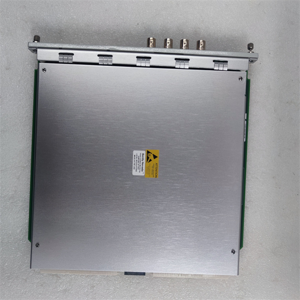
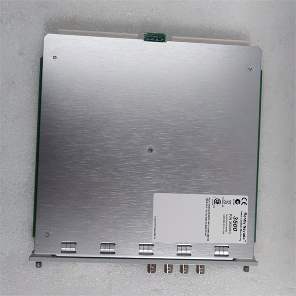
BENTLY 3500/40M 176449-01
The Real-World Problem It Solves
You need continuous protection for critical rotating machinery with vibration and position monitoring in a single module. The 176449-01 handles four channels of proximity transducer inputs, processes multiple measurement types simultaneously, compares against programmable setpoints, and drives alarms when thresholds are exceeded—eliminating the need for multiple single-function monitors.
Where you’ll typically find it:
- Steam turbine-generator sets monitoring radial vibration on two bearing planes (2 probes per bearing × 2 bearings = 4 channels)
- Compressor trains monitoring radial vibration and axial thrust position simultaneously
- Large motor-pump combinations requiring eccentricity monitoring during startup and position tracking during operation
Bottom line: This is the 4-channel proximity monitor for the 3500 rack, handling vibration and position measurements with built-in Ethernet and Modbus communications for seamless integration into DCS/PLC systems.
Hardware Architecture & Under-the-Hood Logic
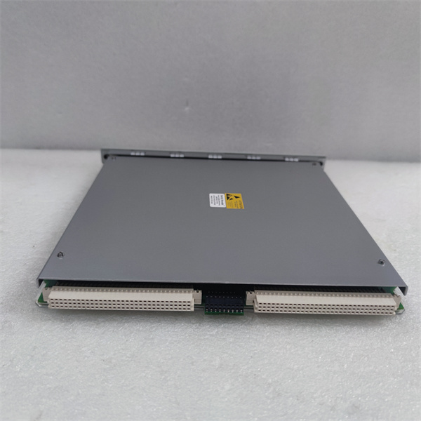
The 176449-01 is a 4-channel monitor module that plugs into the 3500 rack backplane. It receives analog gap voltage signals from Proximitor transducers (via I/O modules), digitizes them using 16-bit ADCs, applies user-configured signal processing algorithms, and outputs alarm status to the rack’s relay modules. Communication with external systems occurs via Ethernet or Modbus RTU interfaces.
-
Signal Reception: Each channel receives a gap voltage signal (-20V to +2V DC) from the connected Proximitor transducer (3300/3300 XL/7200 series) through the I/O module. This signal represents the physical gap between the probe tip and the target surface.
-
Analog-to-Digital Conversion: The incoming analog gap voltage is digitized by a 16-bit ADC at a sampling rate of 10 kHz. The high resolution ensures accurate representation of vibration waveforms and DC position signals.
-
Signal Processing: Digitized signals pass through configurable processing chains depending on the programmed measurement type:
- Radial Vibration: AC-coupled with selectable filtering (1-600 Hz or 1-10 kHz) to extract vibration waveform
- Axial Position: DC-coupled to extract the average gap voltage representing shaft position
- Eccentricity: DC-coupled with low-pass filtering (<25 Hz) to capture slow shaft position changes during startup
-
Alarm Comparison: Processed values are continuously compared against user-programmed Alert and Danger setpoints (configured via 3500 Configuration Software). When a threshold is exceeded, the module triggers the corresponding alarm state.
-
Alarm Output: Alarm status signals are transmitted to the 3500/32 or 3500/33 Relay Modules via the backplane. These modules drive external relay contacts for annunciation and machine trip functions.
-
Communication: Processed data (vibration amplitude, position, alarm status, diagnostic information) is transmitted via Ethernet (TCP/IP) or Modbus RTU (RS-485) to external systems (DCS, PLC, historians). The module supports both polling and event-driven data transmission.
-
Buffered Output: Each channel provides a buffered reproduction of the transducer signal on the rear panel (BNC or terminal block) for connection to external data acquisition systems or portable analyzers without disrupting the primary signal path.
-
Self-Diagnostics: The module continuously monitors its own health and the integrity of connected transducers. Faults detected include:
- Transducer open circuit
- Transducer short circuit
- Out-of-range gap voltage
- Internal module hardware faults
- Communication failures
BENTLY 3500/40M 176449-01
Field Service Pitfalls: What Rookies Get Wrong
Mismatched Channel Pair ConfigurationTechs configure Channel 1 for Radial Vibration and Channel 2 for Axial Position, treating them independently. The 176449-01 requires channels to be programmed in pairs (1-2 and 3-4) with the same measurement type. When channels are mismatched, the module generates configuration errors, and neither channel operates correctly.
- Field Rule: Always program channel pairs with identical measurement types. If you need Radial Vibration on Ch1 and Axial Position on Ch2, you’re out of luck on this module—use different modules or reconfigure your sensor allocation to match paired requirements.
Incorrect Proximitor Scaling ConfigurationRookies install an 8mm 3300 XL probe (200 mV/mil sensitivity) but leave the module configured for the default 5mm probe (100 mV/mil). Vibration readings display at half the actual amplitude, and gap voltage readings are offset by 2 mils. When shaft vibration is actually 12 mils pk-pk, the system shows 6 mils, potentially missing critical alarms.
- Quick Fix: Verify probe sensitivity in Configuration Software. For 3300 XL 8mm probes, set sensitivity to 200 mV/mil. For 5mm probes, use 100 mV/mil. Cross-check with a handheld calibrator during commissioning—displayed values must match the calibrator’s output within ±5%.
Ignoring Buffered Output Ground IsolationYoung engineers connect a portable data acquisition analyzer to the buffered output BNC connector on the rear panel without isolating the analyzer ground. The analyzer ground creates a ground loop through the buffered output, introducing 60 Hz hum into the measurement. Orbit plots become noisy, and vibration amplitude readings fluctuate randomly.
- Field Rule: Use an isolated differential probe or battery-powered analyzer for buffered output connections. If you must use a grounded analyzer, disconnect the analyzer’s ground pin at the power plug. Measure ground loop voltage with a multimeter—if it exceeds 0.5V AC, you’ve got a loop problem.
Wrong Gap Voltage Range for Axial PositionTechs configure axial position channels using the standard radial vibration range (10-0-10 mils). Thrust bearings typically require ±50 mils or ±80 mils range. When the shaft moves to full thrust position (e.g., +40 mils), the monitor reads 10 mils (saturated), missing the actual position and failing to trigger Danger alarms.
- Field Rule: Set axial position range to match the bearing’s mechanical limits. For most hydrodynamic thrust bearings, use ±50 mils or ±80 mils full-scale. Verify with a feeler gauge at the bearing clearance measurement—monitor should read the same value.
Missing Alarm Time Delay SettingsNovices program Alarm 1 (Alert) and Alarm 2 (Danger) setpoints but leave time delays at zero. Transient vibration spikes during startup or load changes trigger instantaneous alarms, causing nuisance trips and unnecessary shutdowns. Operators bypass alarms to avoid downtime, defeating the protection system.
- Field Rule: Set appropriate time delays based on machine characteristics. For Alert alarms, use 1-3 seconds to filter brief transients. For Danger alarms, use 3-10 seconds to allow operator intervention before automatic trip. Never set Danger delay below 1 second unless the machine has proven tolerance for instant trip.
Improper Shield Grounding on Buffered OutputsTechs ground the shield of cables connected to buffered outputs at both the monitor end and the external analyzer end. This creates ground loops that corrupt the buffered signal with noise. The NOT OK LED flickers intermittently, and the monitor reports “Signal Fault” even though the primary transducer signal is good.
- Quick Fix: Ground shield cables at the analyzer end only. Leave the monitor end shield floating or connected through a capacitor (0.1 µF ceramic) for high-frequency noise rejection. Verify ground potential difference between monitor chassis and analyzer chassis—must be less than 1V AC.
Commercial Availability & Pricing Note
Please note: The listed price is for reference only and is not binding. Final pricing and terms are subject to negotiation based on current market conditions and availability.


