
Description
Hard-Numbers: Technical Specifications
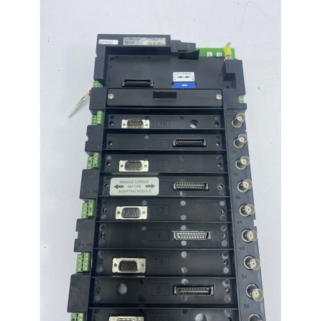
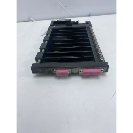
- Module Type: Terminal Base (passive mounting platform)
- Slot Capacity: Accommodates multiple FieldMonitor modules (monitor, I/O, power, interface modules)
- Electrical Connection: Backplane provides -24V DC and +5V DC power distribution from 1701/10 power module
- Backplane Communication: Passes data to network adapter (02200XXX) via Flex I/O compatible interface
- Operating Temperature: -40°C to +70°C (-40°F to +158°F)
- Storage Temperature: -40°C to +85°C (-40°F to +185°F)
- Humidity Range: 5% to 95% non-condensing RH
- Isolation: No isolation (passive backplane – isolation provided by individual modules)
- Power Distribution: Passes power from 1701/10 supply to installed modules
- Dimensions: Matches Allen-Bradley Flex I/O form factor (standard industrial terminal base size)
- Weight: Varies by configuration (base plus installed modules)
- Compliance: CSA/NRTL/C, CE marked (with appropriate module options)
BENTLY 1701/05
The Real-World Problem It Solves
Centralized monitoring systems require expensive home-run cabling from every sensor to a single rack room. The 1701/05 terminal base enables distributed I/O architecture, letting you mount FieldMonitor modules right next to the machinery package and run a single network cable back to the control room instead of individual sensor wires.
Where you’ll typically find it:
- Compressor skid packages where local monitoring is preferred over long sensor runs to the main rack
- Turbine-generator auxiliaries with distributed measurement points requiring local signal conditioning
- Pump stations and remote equipment locations where running individual shielded pairs is cost-prohibitive
Bottom line: This is the mounting platform that makes FieldMonitor’s distributed architecture work—no active circuitry, just reliable power and data distribution to the modules that do the actual monitoring.
Hardware Architecture & Under-the-Hood Logic
The 1701/05 is a passive terminal base with no active electronics. Its job is simple: physically secure FieldMonitor modules and provide electrical connections between them. The backplane distributes DC power from the 1701/10 power supply and passes communication signals between modules and the network adapter.
-
Power Distribution: The -24V DC and +5V DC from the 1701/10 power module enter the base through power connectors and are routed to each module slot via the backplane bus. No regulation or conversion happens here—it’s straight power pass-through.
-
Backplane Communication: The Flex I/O compatible backplane passes data between installed modules and the network adapter (02200XXX). Modules communicate via the backplane bus, which carries serial data to the host control system (PLC/DCS).
-
Module Detection: The base has mechanical keying and electrical contacts that identify installed modules to the system. When a module slides in, it makes contact with backplane fingers, establishing power and data connections.
-
Daisy-Chain Capability: Multiple terminal bases can be linked together to expand channel count. The backplane supports expansion by connecting additional bases via inter-base cables.
-
Ground Reference: The base provides a common ground plane for all installed modules, ensuring consistent signal referencing across the distributed I/O node.

BENTLY 1701/05
Field Service Pitfalls: What Rookies Get Wrong
Mixing Terminal Base Types in the Same SystemTechs grab whatever base is on the shelf—1701/05 or 1701/06 Isolator Terminal Base—without checking whether galvanic isolation is required. The 1701/06 is for hazardous areas with intrinsic safety requirements; 1701/05 is for standard areas. Using the wrong base either wastes money (over-speccing with isolation where not needed) or violates safety codes (using non-isolated base where barriers are required).
- Field Rule: Check the area classification before installation. Use 1701/05 for Division 2/Zone 2 general areas. Use 1701/06 only when you need intrinsic safety for Division 1/Zone 1 transducer locations. Never swap them mid-project without engineering review.
Improper Grounding of the Terminal BaseGreenhorns mount the base on painted cabinet panels or plastic DIN rails without a solid ground connection. The modules reference ground through the base, and poor grounding creates noise, erratic readings, or intermittent faults. The FAULT LED flickers randomly on one channel but not others.
- Quick Fix: Scrape paint off the mounting surface or use a grounding stud. Verify continuity from the base ground terminal to the cabinet earth ground with a multimeter before powering up. If the base floats, you’ll chase phantom faults all day.
Forcing Modules into the Wrong Slot OrientationRookies try to jam modules in backward or upside down when working in tight cabinet spaces. The 1701/05 has keyed slots for a reason—polarized connectors prevent reverse insertion. Forcing it bends the backplane fingers and destroys the base. I’ve seen techs snap off connector pins and then wonder why the module won’t seat.
- Field Rule: Look at the keyed guide pins on the base and the matching slots on the module. If it doesn’t slide in smooth, don’t push harder. Rotate it 180 degrees or check the orientation mark. A $200 base costs more than your pride when you crack it.
Over-Tightening Mounting Screws and Cracking the PlasticYoung engineers torque down the mounting screws like they’re securing cylinder heads on a Detroit Diesel. The 1701/05 base is molded plastic—over-tightening cracks the housing or warps the backplane alignment. Modules won’t seat properly, and you get intermittent contact faults that drive you crazy during commissioning.
- Quick Fix: Use a screwdriver with a calibrated torque feel. Snug is enough—no need to strip the threads. If the base flexes or creaks, back off a quarter turn. Plastic doesn’t forgive Hulk-level torque.
Daisy-Chaining Too Many Bases Without Power Budget ReviewTechs string together six terminal bases because the mechanical package has 20 measurement points, assuming the single 1701/10 power module can handle it all. At full load, the voltage sags, and modules on the last base drop offline or show erratic behavior during startup transients.
- Field Rule: Calculate total power draw. Each monitor module consumes around 1.5W, plus transducer excitation. A 1701/10 has limited capacity—check the manual. If you’re pushing 40+ channels across multiple bases, add a second power supply and split the load. Voltage drop kills distributed systems faster than water.
Leaving Dust Covers Off Unused SlotsAfter commissioning, techs pull blank slot covers to “get better airflow” or just lose them in the toolbag. Dust and conductive metal shavings accumulate in empty slots. Six months later, when you slide in a replacement module during a midnight outage, contamination causes short circuits or intermittent faults.
- Field Rule: Keep blank covers (Part Number 139193-01) installed on every unused slot. If one gets lost, order a replacement. Dirty slots cost more than a $5 plastic cover when you’re chasing ghosts at 3 AM.
Commercial Availability & Pricing Note
Please note: The listed price is for reference only and is not binding. Final pricing and terms are subject to negotiation based on current market conditions and availability.


