
Description
Hard-Numbers: Technical Specifications
- Sensing Type: Piezoelectric accelerometer (ICP)
- Measurement Range: ±50g peak acceleration (500 m/s²)
- Sensitivity: 100 mV/g typical (linear frequency range)
- Frequency Response: 0.5 Hz to 15 kHz (±3 dB) flat response
- Output Signal: 0-10V RMS proportional to acceleration
- Voltage Output: 4-20 mA proportional to acceleration (user-configurable scaling)
- Input Power: 12-28V DC (3 mA typical power consumption)
- Signal Conditioning: Built-in charge amplifier and signal filtering
- Isolation: 1500V RMS galvanic isolation between input/output and power
- Operating Temperature: -55°C to +177°C (-67°F to +350°F)
- Storage Temperature: -55°C to +150°C (-67°F to +302°F)
- Humidity: 5% to 95% RH non-condensing
- Cable Length: Standard 5-meter cable (custom lengths up to 30m available)
- Connector: M12 circular connector or integral cable termination
- Weight: 0.5 lbs (0.23 kg)
- Mounting: M6x1 screw or adhesive mounting pad

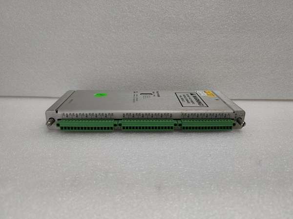
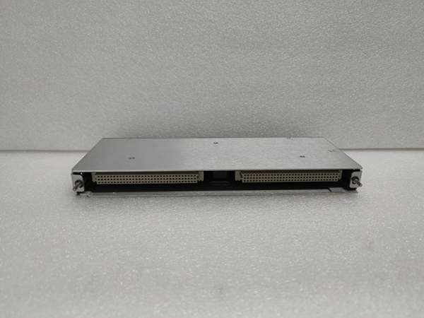
Bently 149992-01
The Real-World Problem It Solves
High-speed turbines and gearboxes exhibit high-frequency faults (gear tooth wear, bearing cage vibration) that fall outside the frequency range of standard proximity probes. The 149992-01 provides a wider bandwidth (0.5-15 kHz) than the 149986-01, enabling detection of early-stage high-frequency faults before they cause catastrophic failure.
Where you’ll typically find it:
- Gas turbine compressor blade vibration monitoring
- Steam turbine and generator bearing wear detection
- Gearbox high-order harmonic analysis for tooth contact
- Centrifugal compressor impeller imbalance monitoring
Bottom line: This is the high-performance accelerometer for the 3300 XL series, providing wider bandwidth and lower noise than the 149986-01 for detecting early machinery faults.
Hardware Architecture & Under-the-Hood Logic
The 149992-01 is an ICP (Integrated Circuit Piezoelectric) accelerometer module. It uses a piezoelectric sensing element to convert mechanical vibration (acceleration) into an electrical charge signal, which is amplified and filtered by built-in electronics to provide a calibrated output.
-
Piezoelectric Sensing Element: The core of the module is a piezoelectric crystal that generates electrical charge proportional to applied acceleration. The crystal material is optimized for high sensitivity across the broad frequency range (0.5-15 kHz).
-
Signal Amplification: An integrated charge amplifier converts the piezoelectric charge signal (femtocoulombs) to a usable voltage (millivolts to volts) while maintaining high input impedance to minimize noise. This removes the need for external charge amplifiers.
-
Signal Filtering: A combination of low-pass (15 kHz) and high-pass (0.5 Hz) filters removes DC drift and high-frequency noise irrelevant to machinery fault detection. The filters are configurable via software to match specific application requirements.
-
Calibration and Output Scaling: Calibration constants stored in non-volatile memory ensure accurate signal output. The module provides both voltage (0-10V RMS) and current (4-20 mA) outputs scaled to match user-configured acceleration ranges.
-
Temperature Compensation: Internal temperature sensors detect module temperature and apply correction factors to calibration constants, minimizing drift across the wide operating temperature range (-55°C to +177°C). This ensures reliable measurement in extreme thermal environments.
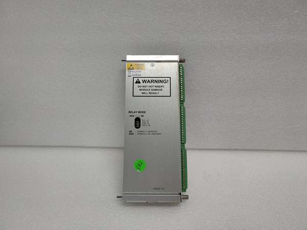
Bently 149992-01
Field Service Pitfalls: What Rookies Get Wrong
Using the Wrong Sensitivity Setting for Frequency RangeThe 149992-01 has a 100 mV/g sensitivity, but some vibration software expects 200 mV/g (typical for older accelerometers). Techs don’t adjust software settings and the monitor displays only half the actual vibration amplitude. Critical 10g vibration shows as 5g, delaying fault detection.
- Field Rule: Always verify software sensitivity settings match the module’s sensitivity. If the module has 100 mV/g, set software to the same sensitivity. If you’re upgrading from an older 200 mV/g sensor, adjust software settings accordingly to prevent under-reporting.
Ignoring Low-Frequency Response During InstallationTechs mount accelerometers directly on rotating shafts thinking it will increase sensitivity, but accelerometers have very low low-frequency response (DC or near-DC). At low speeds (<100 RPM), measurement error increases rapidly. The module measures centrifugal force instead of vibration when mounted on rotating parts.
- Quick Fix: Always mount accelerometers on stationary parts (bearing housings, base frames) for vibration monitoring. If you need to measure shaft vibration, use a proximity probe instead of an accelerometer. The module is designed for measuring vibration frequencies above 1 Hz, not for static measurement.
Poor Cable Installation Induces NoiseI’ve seen techs route accelerometer cables alongside high-voltage power cables or drive motor power leads. EMI from power cables couples into the accelerometer signal, resulting in noise equivalent to 5-10g RMS vibration, completely masking actual machine vibration signals.
- Field Rule: Route accelerometer cables in separate grounded conduits at least 12 inches away from power cables. Use twisted-pair shielded cable with shields connected only at the module end to avoid ground loops. Use metal conduits or braided shielded cables for high-noise environments like industrial power plants.
Not Verifying Mounting ResonanceThe accelerometer’s mounting resonance frequency (typically >50 kHz for screw mounting) should be well above the highest measured vibration frequency (15 kHz). Techs use adhesive mounting pads on thin aluminum housings, reducing resonance frequency to ~20 kHz. The module’s output peaks at 20 kHz, masking real gear vibration signals.
- Quick Fix: Always use M6 screw mounting for optimal resonance. If you must use adhesive pads, verify resonance frequency is above 20 kHz using a spectrum analyzer. Avoid mounting on thin materials where structural resonance could interfere with measurements. Document mounting method and resonance frequency in maintenance logs.
Overlooking Thermal Effects on SensitivityAt the upper operating temperature (+177°C), sensitivity can vary by up to ±5% (from 100 mV/g to 95 or 105 mV/g). Techs don’t re-calibrate after extended high-temperature operation, leading to misreported vibration amplitudes.
- Field Rule: Perform re-calibration every 6-12 months for accelerometers operating in high-temperature environments (>120°C). Use manufacturer-provided sensitivity tables for different temperatures if re-calibration isn’t feasible. Document temperature trends and apply correction factors as needed.
Incorrect Connector Pinout for Power/OutputTechs wire the accelerometer module to the DCS without verifying connector pinout. The module has power, ground, signal+ and signal- pins, and swapping power and ground pins can damage the internal charge amplifier.
- Field Rule: Always refer to the module’s pinout diagram before wiring. Verify power voltage (12-28V DC) and polarity before energizing. Use a multimeter to confirm voltage levels at module terminals. Label connector pins to prevent mis-wiring during future maintenance.
Commercial Availability & Pricing Note
Please note: The listed price is for reference only and is not binding. Final pricing and terms are subject to negotiation based on current market conditions and availability.


