
Description
Hard-Numbers: Technical Specifications
- Sensing Type: Piezoelectric accelerometer (ICP)
- Range: ±50g (500 m/s²) peak acceleration
- Sensitivity: 100 mV/g typical (linear frequency range)
- Frequency Response: 10 Hz to 10 kHz (±3 dB) flat response
- Output Signal: 0-10V RMS proportional to acceleration
- Voltage Output: 4-20 mA proportional to acceleration (user-configurable)
- Input Power: 24V DC ±1V (2 mA typical power consumption)
- Signal Conditioning: Built-in charge amplifier and signal filtering
- Isolation: 1500V RMS galvanic isolation between input/output and power
- Operating Temperature: -40°C to +121°C (-40°F to +250°F)
- Storage Temperature: -55°C to +150°C (-67°F to +302°F)
- Humidity: 5% to 95% RH non-condensing
- Cable Length: Standard 10-meter cable (custom lengths up to 30m available)
- Connector: M12 circular connector or integral cable termination
- Weight: 0.3 lbs (0.14 kg)
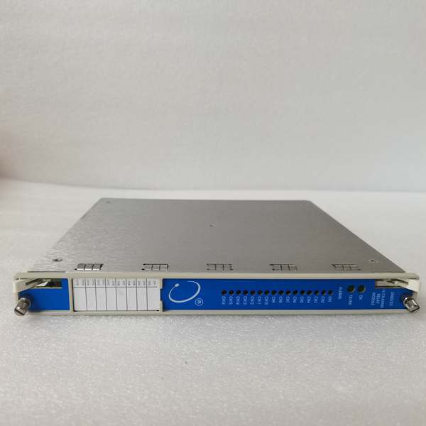
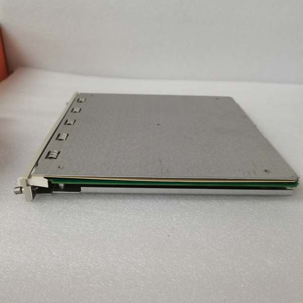
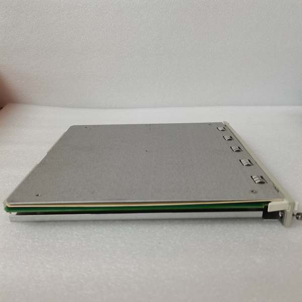
Bently 149986-01
The Real-World Problem It Solves
High-speed machinery (turbines, compressors) develop high-frequency faults (e.g., bearing cage wear, gear tooth damage) that standard eddy current probes don’t detect at typical vibration ranges. The 149986-01 measures high-frequency vibration up to 10 kHz, enabling early detection of these faults before catastrophic failure.
Where you’ll typically find it:
- Gas turbine bearing high-frequency monitoring
- Centrifugal compressor rotor imbalance detection
- Gearbox tooth damage analysis (high-order harmonics)
- High-speed pump cavitation monitoring
Bottom line: This is the high-frequency accelerometer module for the 3300 XL series, providing wide-bandwidth vibration measurement for fault detection in high-speed equipment.
Hardware Architecture & Under-the-Hood Logic
The 149986-01 is an ICP (Integrated Circuit Piezoelectric) accelerometer module. It contains a piezoelectric sensing element, integrated charge amplifier, signal filter, and calibration memory. The piezoelectric element generates electrical charge proportional to acceleration. The charge amplifier converts charge to voltage, filters out noise, and provides a calibrated 0-10V RMS output signal proportional to acceleration.
-
Piezoelectric Sensing: The core piezoelectric element changes charge output in proportion to applied acceleration. This principle enables wide-bandwidth (DC to >10 kHz) acceleration measurement.
-
Signal Amplification: Integrated charge amplifier converts piezoelectric charge signal (femtocoulombs) to usable voltage (millivolts to volts) while maintaining high impedance. This eliminates external signal conditioner requirements.
-
Signal Filtering: Built-in filters (low-pass 10 kHz, high-pass 10 Hz) remove DC drift and high-frequency noise irrelevant to machinery faults. Filter cutoffs can be adjusted via external calibration software.
-
Signal Output: Calibration constants stored in memory ensure accurate acceleration to voltage conversion. The module provides both 0-10V RMS proportional to acceleration and a 4-20 mA scaled output for DCS/SCADA systems.
-
Temperature Compensation: Integrated temperature sensors correct calibration drift across the operating temperature range (-40°C to +121°C). This ensures accurate measurement in extreme thermal environments typical in turbine halls.
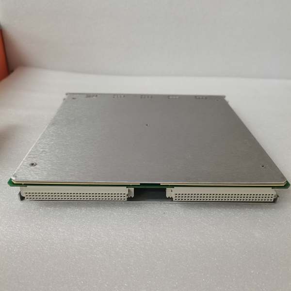
Bently 149986-01
Field Service Pitfalls: What Rookies Get Wrong
Mounting Orientation Critical for SensitivityTechs mount the accelerometer on the top of the bearing housing thinking it’s just as good as side mounting. But accelerometers are sensitive to gravity—top mounting introduces gravity bias, and sensitivity changes with sensor orientation. I’ve seen sensitivity drop by 10% because of vertical mounting where horizontal mounting was specified.
- Field Rule: Always mount accelerometers in the direction (horizontal/vertical) specified in installation drawings. If orientation is changed during maintenance, recalibrate or apply a correction factor (use manufacturer-provided sensitivity tables for different orientations).
Forgetting to Ground Cable ShieldAccelerometer cables carry low-level signals susceptible to electromagnetic interference (EMI) from nearby power cables or drive motors. Techs don’t ground the cable shield, and 60 Hz noise appears as vibration on the signal.
- Quick Fix: Connect cable shield to the module’s ground terminal at only one end (module side, not sensor end) to avoid ground loops. Keep cables away from high-power wiring (minimum 12-inch separation). Use twisted-pair shielded cable with grounding rings on connectors for secure shielding.
Not Verifying Frequency Response During CommissioningTechs assume the accelerometer’s 10-10 kHz frequency response is correct out of the box. But without verifying, you might have mismatched output filter settings. For example, if you’re monitoring gear tooth vibration around 5 kHz and the output filter is set to 3 kHz, you’ll miss the actual fault frequency.
- Field Rule: Use a vibration analyzer or spectrum analyzer to verify the module’s frequency response during commissioning. Inject known vibration frequencies across the 10-10 kHz range and confirm output voltage matches sensitivity. Adjust filter settings in software if response doesn’t match expectations.
Mixing Acceleration and Displacement SignalsTechs connect accelerometer output to a monitor expecting displacement (eddy current probe) signal. The accelerometer outputs acceleration (g), not displacement (mm/mils). Monitoring software sees high-amplitude signals and misinterprets minor vibration as severe damage.
- Field Rule: Ensure the monitoring software is configured for acceleration, not displacement, when using accelerometers. Convert acceleration to velocity (integrate once) or displacement (integrate twice) in software if desired, but don’t mix signal types in a single monitoring channel.
Overlooking Thermal Effects on CalibrationThe module’s calibration drift with temperature is typically ±1% over its operating range. But at the upper limit (+121°C), drift can reach ±5% (0.05V/g error for 100 mV/g sensitivity). Techs install the sensor in hot bearing housings (>100°C) without periodic re-calibration, leading to false positives/negatives.
- Field Rule: Monitor module temperature using built-in temperature sensors (if available) and schedule calibration at upper-temperature extremes. For sensors installed on hot components, perform zero-offset checks after reaching operating temperature to account for thermal drift. Use software to apply temperature correction factors if required.
Incorrect Cable Length ConsiderationsICP accelerometers require a minimum current (1-2 mA) to power the integrated charge amplifier. Cables longer than 30 meters can cause voltage drop, leading to insufficient power supply for the sensor.
- Field Rule: Follow manufacturer cable length guidelines. ICP accelerometers typically have max cable length limits: 10 meters with integrated termination, 30 meters with separate termination. If longer cables are required, use signal repeaters or drive amplifiers to maintain signal integrity.
Commercial Availability & Pricing Note
Please note: The listed price is for reference only and is not binding. Final pricing and terms are subject to negotiation based on current market conditions and availability.


