
Description
Hard-Numbers: Technical Specifications
- Compatible Probes: 3300 XL 5mm proximity probes (e.g., 135489-02, 136709-01)
- Excitation Output: -24V DC ±1V (3 to 12 mA per channel)
- Linear Range: 0.25 to 1.5 mm gap (10 to 60 mils)
- Sensitivity: 200 mV/mil (7.87 V/mm) typical at mid-gap (35 mils or 0.89 mm)
- Frequency Response: DC to 10 kHz (±3 dB) for vibration output
- Signal Outputs:
- Gap Voltage (DC): -18V at 0.25 mm, -2V at 1.5 mm
- Vibration (AC): 0-10V RMS proportional to displacement
- Input Impedance: High impedance (>1MΩ) for probe coil input
- Isolation: 1500V RMS galvanic isolation between input/output and power circuits
- Operating Temperature: -30°C to +65°C (-22°F to +149°F)
- Storage Temperature: -40°C to +85°C (-40°F to +185°F)
- Humidity: 5% to 95% RH non-condensing
- Power Supply: -24V DC ±1V (external Proximitor power module or 3500 rack)
- Power Draw: 1.5W typical (per channel with probe connected)
- Dimensions: 2.5″ H × 2.5″ W × 1.0″ D (compact module body)
- Weight: 0.2 lbs (0.09 kg)
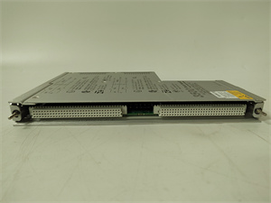
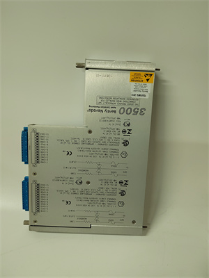
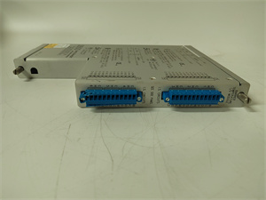
BENTLY 136711-01
The Real-World Problem It Solves
Small diameter shafts or tight-clearance machinery need non-contact vibration monitoring but won’t fit an 8mm probe or Proximitor module. The 136711-01 provides compact signal conditioning for 5mm probes, enabling installation in confined spaces while maintaining high accuracy in critical auxiliary machinery.
Where you’ll typically find it:
- Gearbox bearing vibration monitoring
- Small pump and motor shaft position monitoring
- Auxiliary turbine and high-speed blower monitoring
- Machine tool spindle vibration measurement
Bottom line: This is the 5mm Proximitor for 3300 XL 5mm probes, providing calibrated signals for small shafts where space is limited.
Hardware Architecture & Under-the-Hood Logic
The 136711-01 is a 5mm Proximitor designed specifically for 3300 XL 5mm proximity probes. It contains a high-frequency oscillator, impedance measurement circuit, gap voltage converter, vibration filter, and calibration circuits. The Proximitor supplies -24V DC excitation, measures coil impedance changes, and converts these to DC gap voltage and AC vibration signals in a compact package.
-
High-Frequency Oscillator: The Proximitor generates a high-frequency AC signal (typically 1 MHz) optimized for smaller 5mm probe coils. This drives the magnetic field at the probe tip.
-
Coil Impedance Measurement: As the shaft gap changes, eddy currents alter coil impedance. The Proximitor uses high-sensitivity impedance bridges to measure these changes, providing resolution suitable for small linear ranges (0.25-1.5 mm gap).
-
Gap Voltage Conversion: Measured impedance is converted to DC gap voltage linear across the probe’s working range (0.25-1.5 mm). The Proximitor uses lookup tables to compensate for probe non-linearities.
-
Vibration Signal Extraction: A high-pass filter (10 Hz cutoff) extracts AC vibration from the DC gap voltage signal. The vibration output is buffered and scaled to 0-10V RMS proportional to shaft displacement.
-
Output Conditioning: The DC gap voltage and AC vibration signals are isolated and buffered to drive downstream monitoring equipment. The compact design is optimized for 5mm probes but can be used with 8mm probes if linear range is adjusted.
Bently 136711-01
Field Service Pitfalls: What Rookies Get Wrong
Using 5mm Proximitor with 8mm ProbesI’ve seen techs use 136711-01 5mm Proximitor with 8mm probes during maintenance because they’re out of 8mm Proximitors. The 5mm module’s oscillator and impedance bridge aren’t optimized for 8mm coils, resulting in reduced sensitivity (150 mV/mil instead of 200 mV/mil) and non-linear range.
- Field Rule: Never cross-family probe/Proximitor pairs. 8mm probes require 8mm Proximitors, 5mm probes require 5mm Proximitors. If you must temporarily use a mismatched pair, recalibrate the linear range carefully and replace with the correct Proximitor at the earliest opportunity.
Ignoring Shorter 5mm Linear RangeRookie engineers use the 8mm probe’s linear range (0.5-2.5 mm) as a reference when calibrating 5mm probes. They set mechanical gap at 0.7 mm (28 mils), which is within the 8mm range but outside the 5mm’s recommended mid-gap (35 mils or 0.89 mm). This causes linearity errors over the full range.
- Quick Fix: Memorize the 5mm probe’s linear range (0.25-1.5 mm gap). Set mechanical gap at mid-range (0.89 mm or 35 mils), then observe gap voltage should read -10V DC. If not, adjust gap or recalibrate the Proximitor until mid-gap is at -10V.
Not Verifying Signal Output for Small ChangesTechs test vibration output only at full load, assuming it works. But at idle speed (500 RPM), shaft vibration is 0.1 mm (4 mils), and the 5mm Proximitor’s output signal is 0.4V RMS. Without verifying at small amplitudes, you can’t catch gain errors or zero offset that would miss early fault detection.
- Field Rule: Test vibration output at idle speed and at least two load points (partial load and full load). Use a function generator to inject known vibration frequencies into the probe circuit and verify output amplitude matches sensitivity. Adjust Proximitor gain if needed to match calibration targets.
Grounding the Proximitor Chassis to Signal GroundTo avoid signal interference, techs ground the Proximitor chassis to the signal ground. But the Proximitor has galvanic isolation between outputs and chassis. Grounding the chassis to signal ground breaks isolation and introduces ground loop noise into outputs, especially with long probe cables.
- Field Rule: Always keep the Proximitor chassis floating (not connected to any ground reference). The isolation design already prevents ground loops. Use twisted-pair cables with one end grounded (at the Proximitor side) and the other end grounded (at the monitoring equipment) if needed, but don’t ground the module chassis itself.
Forgetting to Adjust Alarm Setpoints for Different SensitivityWhen replacing a probe or changing to a different probe type (e.g., 5mm to 8mm), techs forget to adjust alarm setpoints. The 5mm probe’s sensitivity is 200 mV/mil, same as the 8mm probe, but the linear range is shorter—so the same setpoint represents a different proportion of range.
- Field Rule: After changing probe type, recalculate alarm setpoints based on probe sensitivity and linear range. For example, if you used a setpoint of 5 mils (0.125 mm) on an 8mm probe, this represents 6.25% of range. On a 5mm probe with 40 mils range, this represents 12.5% of range. Adjust setpoints proportionally to match original risk assessment.
Installing Proximitor Too Close to High-Heat SourcesThe Proximitor’s operating temperature range is -30°C to +65°C, which is below some machinery bearing housing temperatures (up to 150°C). Techs install the Proximitor in a bearing housing without sufficient cooling, causing thermal drift or premature failure.
- Field Rule: Mount the Proximitor in a location where ambient temperature remains below 65°C. Use heat sinks or extend probe cables to move the Proximitor away from heat sources. Monitor Proximitor temperature during operation using thermal imaging or built-in temperature sensors if available.
Commercial Availability & Pricing Note
Please note: The listed price is for reference only and is not binding. Final pricing and terms are subject to negotiation based on current market conditions and availability.


