
Description
Hard-Numbers: Technical Specifications
- Compatible Probes: 3300 XL 8mm proximity probes (e.g., 135473-01, 135488-01)
- Excitation Output: -24V DC ±1V (3 to 15 mA per channel)
- Linear Range: 0.5 to 2.5 mm gap (20 to 80 mils)
- Sensitivity: 200 mV/mil (7.87 V/mm) typical at mid-gap (50 mils or 1.27 mm)
- Frequency Response: DC to 10 kHz (±3 dB) for vibration output
- Signal Outputs:
- Gap Voltage (DC): -18V at 0.5 mm, -2V at 2.5 mm
- Vibration (AC): 0-10V RMS proportional to displacement
- Input Impedance: High impedance (>1MΩ) for probe coil input
- Isolation: 1500V RMS galvanic isolation between input/output and power circuits
- Operating Temperature: -30°C to +65°C (-22°F to +149°F)
- Storage Temperature: -40°C to +85°C (-40°F to +185°F)
- Humidity: 5% to 95% RH non-condensing
- Power Supply: -24V DC ±1V (external Proximitor power module or 3500 rack)
- Power Draw: 2W typical (per channel with probe connected)
- Dimensions: 3.5″ H × 2.5″ W × 1.0″ D (module body only)
- Weight: 0.3 lbs (0.14 kg)
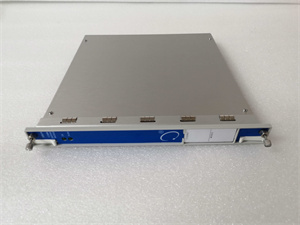
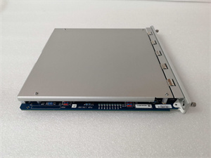
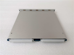
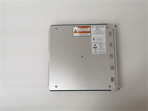
BENTLY 3500/92 136180-01
The Real-World Problem It Solves
A 3300 XL proximity probe alone can’t generate a usable output—it needs signal conditioning to convert coil impedance to readable gap voltage and vibration data. The 136180-01 Proximitor provides excitation voltage, conditions the probe signal, and outputs calibrated DC gap voltage and AC vibration signals that monitoring systems can use.
Where you’ll typically find it:
- Steam turbine generator radial and axial vibration monitoring systems
- Centrifugal compressor and pump shaft position monitoring
- Standalone machinery protection panels with 3300 XL transducers
Bottom line: This is the signal conditioner that makes 3300 XL 8mm proximity probes work—providing excitation, signal processing, and calibrated outputs for protection systems.
Hardware Architecture & Under-the-Hood Logic
The 136180-01 is an 8mm Proximitor designed specifically for 3300 XL 8mm proximity probes. It contains a high-frequency oscillator, coil impedance measurement circuit, gap voltage converter, vibration filter, and calibration circuits. The Proximitor supplies -24V DC excitation to the probe, measures coil impedance changes caused by shaft gap variations, and converts these changes to DC gap voltage (position) and AC vibration signals.
-
High-Frequency Oscillator: The Proximitor generates a high-frequency AC signal (typically 500 kHz to 1 MHz) that drives the probe coil. This AC signal creates the eddy current field at the probe tip.
-
Coil Impedance Measurement: As the probe gap changes, eddy currents in the shaft alter the coil impedance. The Proximitor measures this impedance change using a synchronous demodulation circuit, converting impedance to a proportional DC voltage.
-
Gap Voltage Conversion: The measured impedance is converted to DC gap voltage linear across the probe’s working range (0.5-2.5 mm). The Proximitor applies calibration constants stored in memory to compensate for non-linearities in probe performance.
-
Vibration Signal Extraction: The DC gap voltage contains both position information (slow changes) and vibration information (rapid changes). A high-pass filter (typically 10 Hz cutoff) extracts the AC vibration component, while a low-pass filter isolates the DC position component.
-
Output Conditioning: The conditioned gap voltage and vibration signals are buffered and output as isolated signals. The vibration output can be scaled (0-10V RMS) for direct connection to monitoring systems. The gap voltage output provides shaft absolute position for DCS trending or alarm input.
-
Temperature Compensation: The Proximitor includes temperature compensation circuits to minimize calibration drift across its operating temperature range (-30°C to +65°C). This ensures stable gap voltage output even as ambient temperature changes.
Field Service Pitfalls: What Rookies Get Wrong
Using the Wrong Proximitor for Probe SizeI’ve seen techs use an 8mm Proximitor (136180-01) with a 5mm probe (135489-02) thinking they’re interchangeable. The sensitivity curves don’t match—gap voltage at mid-gap reads -12V instead of -10V, and vibration amplitude is off by 25%.
- Field Rule: Always match Proximitor part number to probe diameter. 8mm probes (135473-01, 135488-01) require 8mm Proximitors (136180-01). 5mm probes (135489-02) require 5mm Proximitors (different part number). Verify the suffix on the Proximitor label matches the probe size before energizing.
Incorrect Wiring of Proximitor OutputsTechs connect the vibration output to a DCS analog input expecting gap voltage. The DCS sees fluctuating 0-10V AC signal and interprets it as erratic position changes, triggering nuisance alarms. Worse, they wire gap voltage to a vibration analyzer expecting AC signals—the analyzer shows no vibration because it’s receiving DC.
- Field Rule: Verify which output terminal provides gap voltage (DC) versus vibration (AC). Use a multimeter to confirm: gap voltage should read steady DC (e.g., -10V at mid-gap), vibration output should read near 0V DC with AC voltage present when machine is running. Label terminal connections clearly to prevent confusion.
Forgetting to Set Mid-Gap Voltage During CalibrationRookie engineers replace a probe but skip mid-gap voltage setting, assuming factory calibration is close enough. Mid-gap voltage drifts by ±2V due to probe-to-probe variation, resulting in ±0.4 mm (±16 mils) measurement error. At 10,000 RPM, that’s a significant error in shaft position monitoring.
- Quick Fix: After installing a new probe, set mechanical gap to mid-range using a feeler gauge (typically 1.27 mm or 50 mils for 8mm probes). Observe gap voltage at the Proximitor output—if it deviates from -10V by more than ±1V, recalibrate the Proximitor or adjust mechanical gap slightly to achieve -10V. Document the actual mid-gap voltage for future reference.
Not Verifying Frequency Response During CommissioningTechs assume the Proximitor’s frequency response (DC to 10 kHz) covers all machinery vibration frequencies. But on high-speed gearboxes running at 20,000 Hz mesh frequency, the 8mm Proximitor’s -3 dB point (10 kHz) attenuates signal by 50% or more.
- Field Rule: Verify the highest frequency you need to monitor is within the Proximitor’s frequency response (DC to 10 kHz for 8mm Proximitors). For frequencies above 10 kHz, consider using a high-frequency Proximitor variant or a different transducer type (e.g., accelerometer). Test frequency response using a function generator and oscilloscope during commissioning.
Grounding the Output Terminal to ChassisI’ve seen techs ground the Proximitor output terminal to the chassis ground to “stabilize the signal.” This creates a ground loop between the Proximitor output and the monitoring system input, resulting in 60 Hz hum riding on the vibration signal.
- Field Rule: Never ground the Proximitor output terminals. The Proximitor provides isolated outputs specifically to prevent ground loops. Connect output wires to the monitoring system’s floating input terminals. If you must reference to ground, use a differential input with proper isolation, not a direct chassis ground.
Ignoring Temperature-Induced DriftProximitors drift with temperature—about 1% of full scale per 20°C change in ambient temperature. In a hot turbine hall (50°C ambient), gap voltage drifts by ±0.25 mm (±10 mils) over a year. Techs don’t notice until the turbine trips on thrust bearing wear that isn’t actually there.
- Quick Fix: Perform periodic zero checks at different ambient temperatures. If drift exceeds acceptable limits, relocate the Proximitor to a temperature-controlled cabinet or use a Proximitor with extended temperature compensation. Document drift trends and apply correction factors in software if necessary.
Commercial Availability & Pricing Note
Please note: The listed price is for reference only and is not binding. Final pricing and terms are subject to negotiation based on current market conditions and availability.


