
Description
Hard-Numbers: Technical Specifications
- Probe Size: 8mm tip diameter
- Linear Range: 0.5 to 2.5 mm gap (20 to 80 mils)
- Sensitivity: 200 mV/mil (7.87 V/mm) typical at mid-gap (50 mils or 1.27 mm)
- Excitation Voltage: -24V DC ±1V
- Excitation Current: 3 to 15 mA (5 to 10 mA typical)
- Frequency Response: DC to 10 kHz (±3 dB)
- Operating Temperature: -30°C to +177°C (-22°F to +350°F) (standard probe)
- Cable Length: Standard 5-meter cable (custom lengths available)
- Connector: Miniature coaxial (MS-style) or screw-lock (depending on variant)
- Housing Material: 316 stainless steel probe body
- Environmental Protection: IP67-rated probe tip (when properly sealed)
- Weight: 0.2 lbs (0.1 kg) including cable
- Thread Size: 3/8-24 UNF or M8x1 (variant dependent)
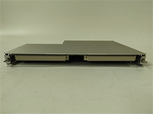
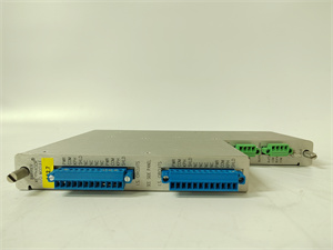
BENTLY 135473-01
The Real-World Problem It Solves
You need to measure shaft vibration and absolute position on high-speed rotating machinery without physical contact that would wear out or add mass to the rotor. The 135473-01 provides non-contact, high-precision measurement of shaft displacement, gap voltage, and vibration using eddy current technology, eliminating mechanical wear and enabling real-time condition monitoring.
Where you’ll typically find it:
- Steam turbine generator radial and axial vibration monitoring (journal bearings)
- Centrifugal compressor and pump shaft position monitoring
- Motor and generator bearing vibration detection in industrial plants
Bottom line: This is the workhorse 8mm proximity probe for the 3300 XL series, providing reliable non-contact vibration and position measurement on critical rotating machinery.
Hardware Architecture & Under-the-Hood Logic
The 135473-01 is an eddy current proximity probe that measures the gap between the probe tip and conductive target surface (shaft). The probe contains a coil that generates a high-frequency magnetic field, inducing eddy currents in the target material. These eddy currents oppose the original field, changing the coil impedance. This impedance change is converted to a DC voltage proportional to gap distance by an external Proximitor sensor. The probe requires -24V DC excitation and outputs a signal proportional to the physical gap.
-
Eddy Current Generation: The probe coil (driven by the Proximitor’s high-frequency oscillator) generates an alternating magnetic field at the probe tip. When the shaft surface enters this field, eddy currents are induced in the conductive shaft material.
-
Impedance Change: The induced eddy currents create an opposing magnetic field that changes the coil impedance. Closer gap = stronger eddy currents = higher impedance change. Farther gap = weaker eddy currents = lower impedance change.
-
Gap Voltage Conversion: The Proximitor measures coil impedance and converts it to a DC gap voltage. This gap voltage is linear across the probe’s linear range (0.5 to 2.5 mm). Typical output: -18V at 0.5 mm gap, -2V at 2.5 mm gap.
-
Signal Conditioning: The Proximitor amplifies and conditions the gap voltage signal, filtering noise and providing outputs for vibration (AC component) and position (DC component). Vibration is extracted using a high-pass filter (typically 10 Hz cutoff), while position is the DC gap voltage level.
-
Temperature Compensation: The probe’s calibration is temperature-dependent. The 135473-01 includes temperature compensation in the Proximitor to minimize drift across the operating temperature range (-30°C to +177°C).
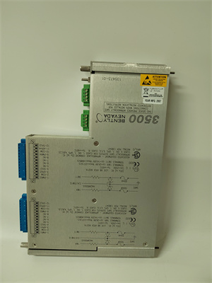
BENTLY 135473-01
Field Service Pitfalls: What Rookies Get Wrong
Incorrect Mechanical Gap During InstallationTechs set the mechanical gap too close or too far from mid-gap. They set it at 0.2 mm (8 mils) thinking “closer is better,” but this is outside the linear range and causes signal saturation. Or they set it at 4 mm (160 mils), which is way too far—no usable signal at all.
- Field Rule: Always set mechanical gap at mid-range of the probe’s linear range (typically 1.27 mm or 50 mils for 8mm probes). Use a feeler gauge or dial indicator to verify gap before securing the probe. Observe the resulting gap voltage—it should be around -10V DC at mid-gap for 3300 XL 8mm probes.
Installing on Non-Conductive or Rough Shaft SurfacesRookie engineers install eddy current probes on stainless steel shafts with high chrome content, which has poor eddy current response. Or they install on shaft surfaces with pitting, scoring, or mechanical runout from previous damage. The signal fluctuates ±0.5 mm even though actual shaft position is stable.
- Quick Fix: Verify target material is conductive and suitable for eddy current measurement (low-alloy steel works best). Inspect the shaft surface for mechanical imperfections. If runout exceeds 0.05 mm (2 mils), the probe will see mechanical runout as false vibration. Install probes on smooth, conductive surfaces or add a target ring (collar) if necessary.
Mixing Probe and Proximitor FamiliesI’ve seen techs use a 135473-01 3300 XL probe with an older 3300 Series Proximitor instead of the correct 3300 XL Proximitor. The sensitivity curves don’t match, leading to measurement errors up to 20%. Gap voltage shows -8V when actual gap is 1.27 mm.
- Field Rule: Always use matching probe and Proximitor families. 3300 XL probes must be used with 3300 XL Proximitors. Older 3300 Series probes must be used with 3300 Series Proximitors. Verify the Proximitor part number matches the probe family before energizing.
Ignoring Cable Length Limits3300 XL probes have a maximum cable length to maintain signal integrity. Techs run 15-meter cables without considering the Proximitor-to-probe capacitance, leading to signal attenuation and measurement errors. The gap voltage drops below -18V at minimum gap due to wire resistance.
- Field Rule: Follow Bently’s cable length guidelines: max 5 meters for 3300 XL 8mm probes with standard Proximitor, max 10 meters with extended-range Proximitor. If longer runs are required, use a signal repeater or move the Proximitor closer to the probe. Test signal quality at the Proximitor terminals after wiring.
Forgetting to Tighten Probe Lock NutAfter adjusting the mechanical gap, techs don’t properly torque the probe lock nut. During machine operation, vibration gradually loosens the probe, changing the gap and causing apparent drift in vibration readings. Over time, the probe drifts out of its linear range entirely.
- Quick Fix: Always torque the probe lock nut to manufacturer specification after setting the gap (typically 5–7 Nm). Apply thread-locking compound (e.g., Loctite 242) if vibration is excessive. During PMs, verify lock nut torque with a torque wrench.
Not Replacing Probe with Bent TipDuring maintenance, techs notice the probe tip is slightly bent from mechanical contact with the shaft but reuse it anyway. A bent tip changes the effective gap and creates non-linear eddy current response. The probe shows gap voltage fluctuation ±0.2 mm with no actual shaft movement.
- Field Rule: Inspect probe tips carefully during outages. Any visible bend, nick, or damage means replace the probe. A bent tip cannot be corrected—just order a new one. Verify the new probe has the same part number and calibration as the original.
Commercial Availability & Pricing Note
Please note: The listed price is for reference only and is not binding. Final pricing and terms are subject to negotiation based on current market conditions and availability.


