
Description
Hard-Numbers: Technical Specifications
- Channels: 2 independent transducer channels
- Transducer Type: 3300 XL series proximity probes (8mm or 5mm systems), velocity transducers
- Excitation: -24V DC for proximity probes (5mA max per channel)
- Signal Conditioning: Active filtering (low-pass 1000 Hz), isolation for ground loop prevention
- Voltage Input Range: ±15V DC for proximity probe gap voltage, ±5V DC for velocity transducer output
- Isolation Rating: 1500V RMS between channels and backplane circuits
- Operating Temperature: 0°C to +50°C
- Storage Temperature: -40°C to +85°C
- Humidity: 5% to 95% RH non-condensing
- Power Supply: 24V DC via system backplane
- Power Draw: 3W typical (2 channels with probes connected)
- Dimensions: Standard rack module form factor (3.5″ H × 5.0″ W × 1.0″ D)
- Weight: 0.5 lbs (0.2 kg)
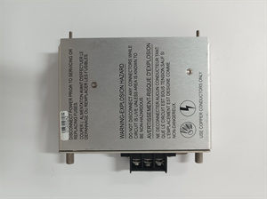
- Field Wiring: Screw terminal blocks for transducer connections
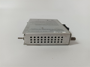
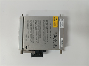
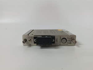
BENTLY 125840-01
The Real-World Problem It Solves
You need to connect 3300 XL proximity probes to a Bently 3500 rack or standalone monitor, but the probe requires excitation voltage and signal filtering that isn’t provided by raw rack inputs. The 125840-01 module supplies excitation voltage, filters noise, and provides isolated signals for condition monitoring, ensuring accurate readings without ground loops or interference.
Where you’ll typically find it:
- Steam turbine and generator bearing vibration monitoring systems
- Compressor and pump rotor position and thrust bearing wear monitoring
- Machinery protection panels in refineries and petrochemical plants using Bently transducers
Bottom line: This is the transducer interface module for the 3300 XL series, bridging between sensors and the rack to provide accurate, filtered signals for condition monitoring.
Hardware Architecture & Under-the-Hood Logic
The 125840-01 is a dual-channel transducer I/O module for Bently 3300 XL proximity probes and velocity transducers. It provides excitation voltage to proximity probes, conditions incoming signals with low-pass filtering, and converts raw signals to a usable range for downstream monitoring equipment. Both channels are galvanically isolated to prevent ground loops and cross-channel interference.
-
Excitation and Signal Reception: The module supplies -24V DC excitation voltage to external proximity probes. The probe outputs a voltage proportional to the gap between probe tip and target shaft (typically -18V at far gap, -2V at close gap). This raw gap voltage enters the module through screw terminal blocks and passes through input protection (surge protection, reverse polarity blocking).
-
Signal Conditioning: The raw gap voltage is filtered using active low-pass filters (1000 Hz cutoff frequency) to remove electrical noise and high-frequency vibrations irrelevant to condition monitoring. Filtered signals are amplified to match the input range requirements of downstream monitor modules.
-
Gap Voltage to Displacement Conversion: The module includes calibration logic that converts gap voltage to physical displacement (mils or mm). This conversion uses lookup tables stored in module memory to compensate for non-linearities in probe performance. Conversion results are sent as scaled analog outputs or directly to downstream monitor modules via bus interface.
-
Isolation and Ground Loop Prevention: Each transducer channel is galvanically isolated from the module backplane and from the other channel to prevent ground loops between sensors and monitoring equipment. Isolation eliminates signal errors caused by different ground potentials in large machinery installations.
-
Health Monitoring and Fault Detection: The module continuously monitors transducer signal quality and health. It detects open circuits, short circuits, probe disconnected conditions, and signal out of range faults. Fault status is reported via a status LED on the module front panel and can trigger relay alarms if configured.
BENTLY 125840-01
Field Service Pitfalls: What Rookies Get Wrong
Connecting Velocity Transducers to Proximity ChannelsI’ve seen techs wire velocity transducers (which output AC voltage proportional to velocity) to 125840-01 channels configured for proximity probes (which expect DC gap voltage). The module’s input conditioning can’t handle AC signals properly, leading to no valid reading or fluctuating voltage values that mimic vibration.
- Field Rule: Verify transducer type and channel configuration before wiring. Velocity transducers should be connected to dedicated velocity transducer inputs if available. If using a proximity module for velocity signals, configure the channel for velocity input in software, and ensure the transducer is AC coupled.
Incorrect Excitation Wiring for Proximity ProbesRookie engineers reverse excitation voltage polarity when connecting proximity probes, swapping -24V and common. Proximitor sensors are polarity sensitive and will not operate properly with reversed voltage. You’ll get erratic gap voltage readings or no signal at all.
- Quick Fix: Always verify excitation wiring polarity using a multimeter. Measure between excitation terminal and common—should read -24V DC. Before energizing, confirm probe-to-target gap using a feeler gauge, then observe gap voltage after connection. Valid gap voltage should be between -2V and -18V for 3300 XL probes.
Ignoring Wiring Length Limits3300 XL proximity probes have a maximum allowed cable length to maintain signal integrity. Techs run 30-meter cables without signal conditioning modules, leading to signal loss and measurement errors. The gap voltage at the module end drops below minimum range due to wire resistance, showing probe disconnected when it’s actually wired correctly.
- Field Rule: Follow Bently’s cable length guidelines: max 15 meters for proximity probes with 8mm systems, max 25 meters with 5mm systems. If longer runs are required, use a signal repeater or move the module closer to the sensor. Test signal quality at the module terminal block after wiring to ensure full range is maintained.
Not Calibrating Transducer After Probe ChangeAfter replacing a proximity probe, techs assume the existing calibration constants in the module will work with the new probe. But probe linearity varies between units, leading to measurement errors up to 10% of full scale. The transducer module shows 8 mils vibration when actual vibration is 9 mils.
- Field Rule: Always recalibrate the transducer channel after probe replacement. Use a feeler gauge to set known gap distances, and read gap voltage at module terminals. Adjust calibration constants to match probe performance curve for accurate vibration and position measurements.
Mismatched Filter Setting for Velocity vs. Proximity SensorsThe module uses 1000 Hz low-pass filter for proximity probe vibration signals, which is correct for monitoring mechanical vibration. But techs apply the same filter setting to velocity transducers measuring hydraulic oil whirl (which is typically 50-200 Hz). This filters out the actual frequency content you’re trying to monitor, leading to false negatives in vibration analysis.
- Field Rule: Adjust filter cutoff based on transducer type. Use 1000 Hz for proximity probes (mechanical vibration), 100 Hz for velocity transducers (low-frequency vibrations like oil whirl). Verify frequency response in test setup before deploying on machinery.
Wiring Transducers Without ShieldingProximity probe cables carry low-voltage, high-impedance signals that are highly susceptible to electrical noise from nearby power cables. Techs unshielded transducer cables alongside 480V power wiring in the same conduit. The module picks up 60 Hz hum that overwhelms the actual vibration signal, resulting in fluctuating gap voltage readings and false alarms.
- Field Rule: Always use shielded, twisted-pair cables for all transducer wiring. Connect shield at module end only to avoid ground loops. Route transducer cables in separate, grounded conduits at least 12 inches away from power cables. Use conduit separators or dedicated raceways for signal wiring.


