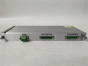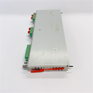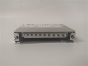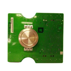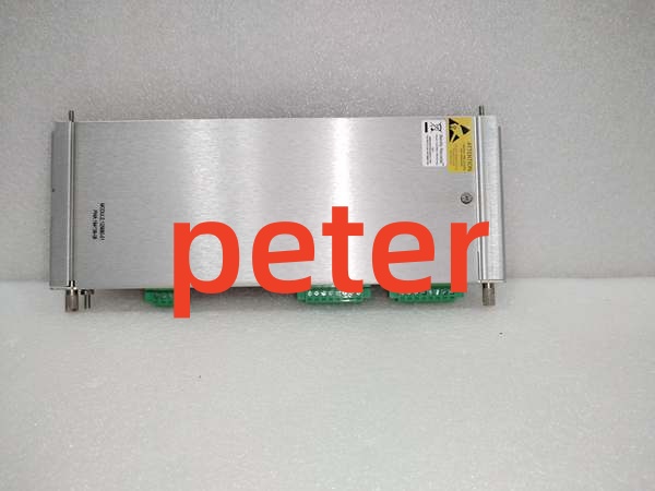
Description
Product Core Brief
- Model: 125720‑01
- Brand: BENTLY
- Series: 3500 Machinery Protection System
- Core Function: Provides four programmable SPDT relay outputs for alarm and trip logic driven by rack‑resident monitoring channels.
- Product Type: Relay Output Module (3500/32)
- Key Specs: 4×Form‑C contacts | 5A@250VAC resistive | Full‑height rack slot
Note: OEM discontinued; available as new surplus and field‑tested used stock.
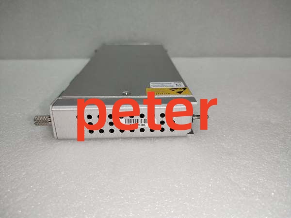
Bently 125680-01
Key Technical Specifications
- Relay Outputs: 4 independent SPDT (Form‑C) dry‑contact channels
- Contact Rating: 5 A resistive @250 VAC, 5 A resistive @30 VDC
- Logic Functions: User‑configurable AND / OR voting, latching, time‑delay parameters
- Backplane Power Draw: 280 mA @ +24 VDC
- Isolation: 2.5 kV isolation between relay contacts and rack logic circuits
- Form Factor: Full‑height slot for 3500‑series rack
- Operating Temperature: ‑30 °C to +65 °C
- Weight: 0.40 kg
- Dimensions: 241 mm × 99 mm × 24 mm
- Compliance: API 670, SIL 2 capable within complete system assessment
Product Introduction
This is a relay‑output I/O board for the 3500 rack. It receives alarm and danger status signals across the backplane from other monitoring cards and drives external field contacts for alarms, trip interlocks, and plant‑system notifications.
Each relay can map to any combination of rack channels. Configurable boolean voting reduces false‑trip risk on turbine and compressor protection setups.
QA & Testing SOP
- Incoming Inspection: Match part number and serial number against OEM documentation. Inspect PCB for relay‑coil burn marks, cracked solder joints, and counterfeit marking defects. Log serial numbers for traceability.
- Live Testing: Seat inside genuine 3500 rack, apply rated backplane power. Establish comms handshake with rack controller. Trigger simulated alarm conditions and verify each relay pulls‑in correctly for continuous 24‑hour load test.
- Electrical Testing: Use Fluke 115 and insulation tester. Verify >10 MΩ isolation between relay field terminals and chassis ground. Confirm chassis‑to‑rack‑earth continuity.
- Firmware/Config Backup: Record exact firmware revision loaded on the unit. Screenshot relay‑logic assignments before reset. Photograph front‑panel LED status for reference.
- Final QC & Packaging: Place unit inside anti‑static shielding bag. Apply printed QC pass tag with test‑date stamp. Pack with shock‑absorbent foam for transit.
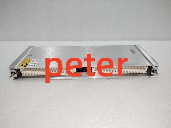
Bently 125680-01
Installation Pitfalls & Guide
❗ Firmware Rev Mismatch: Mismatched rack firmware creates unresponsive relays or random contact chatter. Confirm rack firmware revision matches the firmware running on the unit before commissioning.❗ Slot Location Error: This hardware requires a full‑height rack slot. Partial seating yields intermittent relay operation. Photograph old hardware layout prior to removal.❗ Wiring Incompatibilities: Relay terminal pinout differs from older‑generation relay cards. Cross‑reference OEM datasheet before landing field trip wiring; mis‑wiring can create unsafe trip‑logic behavior.❗ Power Draw Changes: Adding this unit increases total rack backplane load. Calculate aggregate current consumption across all populated slots to avoid overloading rack power supplies.❗ ESD Dangers: Unprotected handling can damage onboard relay‑drive logic. Field cases show ESD‑damaged spare units valued over $2000 before power‑on. Always use grounded ESD wrist straps.
4‑step replacement guide1. Pre‑install: De‑energize rack power, don ESD wrist strap, validate firmware compatibility. Lock‑out external field power connected to relay contacts.2. Removal: Release front‑panel latch, slide out old unit, document every field‑wiring assignment.3. Install: Slide replacement firmly into full‑height slot until latch fully engages. Reconnect field wiring per datasheet pinout.4. Power‑on Test: Restore rack power, confirm backplane communication, inject simulated alarm conditions to validate relay actuation.
FAQ
Q: Does this unit support hot‑swap operation?A: No. It draws power directly from the main system backplane. Live removal produces voltage transients that can corrupt adjacent monitoring cards or damage backplane traces. Full rack power shutdown is mandatory.
Q: Can I switch high‑inductive loads directly from these contacts?A: Contact ratings apply only for resistive loads. Inductive loads such as solenoid coils require external surge suppression. Unsuppressed inductive kickback degrades relay contact life rapidly.
Q: What happens when stored relay‑logic configuration is lost after power‑cycle?A: All voting‑logic assignments live in volatile memory. Power loss erases custom relay mapping. You must reload configuration from the rack configuration tool after power restoration.
Q: Is brand‑new factory stock available?A: Original OEM manufacturing has ceased. Available stock comes from new‑surplus or field‑tested used inventory. Lead‑times shift with lot availability.
Q: What warranty applies to surplus stock?A: Third‑party inventory carries limited‑time functional warranty covering hardware defects. It excludes contact wear from field‑side over‑current events, mis‑wiring, or incorrect configuration. OEM factory warranty is no longer offered.
Q: Can I use this unit within SIL‑rated safety instrumented loops?A: The device supports SIL 2 capability, but this does not equal stand‑alone SIL certification. Complete safety‑system risk assessment must account for voting logic, redundancy, and proof‑test intervals. Verify with OEM datasheet.
Q: Can newer‑generation relay cards serve as drop‑in replacements?A: Physical form factor is similar, but backplane register mapping and relay‑processing logic differ. Direct drop‑in swap is not feasible; rack configuration and field wiring require modification.